Table of Contents
Advertisement
Advertisement
Table of Contents

Related Manuals for Leine Linde MRI 2302


Summarization of Contents
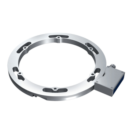
Product Components
Scanning Head Components
Lists individual parts for the scanning head, including mounting holes and indicators.
Flange Mount Components
Details parts for the flange mounting method, such as ring segments and screws.
ClampFit Mount Components
Lists parts for the ClampFit mounting method, including ring segments and tethers.
Product Damage Risks
Product Damage Risk Factors
Details factors like ESD, moisture, extreme temperatures, impacts, and magnetic fields that can damage the product.
Flange Mounting
Fixing with Axial Screws
Procedure for securing the encoder using axial screws on the shaft flange.
ClampFit Mounting
Friction Fitting to Shaft
Method for attaching the encoder via friction fitting to the shaft.
Scanning Head Installation
Align the Scanning Head
Centering the scanning head on the ring's signal centre.
Angle Displacement Tolerance
Maximum permissible angular deviation for the scanning head.
Setting the Air Gap
Using the distance tool to ensure the correct air gap.
Mounting the Scanning Head Unit
Securing the scanning head unit with screws after adjustments.
Mechanical Mounting Checks
Radial Runout and LED Verification
Checking radial runout and confirming the SCANNING LED status.
Electrical Mounting Checks
Shielded Cable Requirements
Guidelines for shielded cables, including earthing, length, and interference.
Cable Bending Radius and Compatibility
Ensuring correct bending radius and avoiding mixing encoder parts.
Accessories
Additional Scanning Head Placement
Instructions for positioning extra scanning heads 180 degrees apart.
Certifications and Approvals
UL/CSA Standards Compliance
Information on UL/CSA testing and product conformity.
CE Marking and EMC Compliance
Details on CE marking and EMC requirements.
Need help?
Do you have a question about the MRI 2302 and is the answer not in the manual?
Questions and answers