Table of Contents
Advertisement
Advertisement
Table of Contents

Subscribe to Our Youtube Channel
Related Manuals for Leine Linde MRI 2202


Summary of Contents for Leine Linde MRI 2202
- Page 2 2000 Encoder series Drehgeber-Serie 编码器系列 Mounting instructions Montageanleitung 安装说明...
- Page 3 SWEDEN / SVERIGE (Head office) Contact T +46-(0)152-265 00 info@leinelinde.se F +46-(0)152-265 05 www.leinelinde.se BRASIL Kontakt T +55-19-3291 8425 info@leinelinde.com.br F +55-19-3367 5658 www.leinelinde.com.br 中国 联系我们 T +86-(021)-52 58 35 66 info@leinelinde.cn F +86-(021)-52 58 35 99 www.leinelinde.cn DANMARK T +45-862-308 34 info@leinelinde.dk www.leinelinde.dk DEUTSCHLAND...
- Page 4 Leine & Linde is a Swedish company dedicated to production of encoders and accessories for heavy duty applications. Some of the values offered by Leine & Linde are local technical support and pos- sibility of 24 hours express delivery. On our website www.leinelinde.com you can find data sheets and other product information.
- Page 5 Leine & Linde AB claims copyright on this documen- tation. It is not allowed to modify, extend or to hand over to a third party and/or copy this documentation without written approval from Leine & Linde AB. Specifications and content in this document are subject to change without prior notice due to our continuous strives to improve functionality and performance of our products.
-
Page 6: Table Of Contents
1. Risk of bodily injury ____________________ page 7 2. Parts of the products ________________________ 8 Contents 3. Risk of damage to the product ______________ 10 4. Flange and ClampFit mount ________________ 12 5. Scanning head mounting ___________________ 16 6. Check points for mechanical mounting _____ 20 Inhalt 7. - Page 7 MRI 2202 The following models are fully covered by these mounting instructions: MRI 2206 MRI 2302 Folgende Modelle werden vollständig von dieser MRI 2306 Montageanleitung abgedeckt: 本安装说明全面涵盖下列型号: MRI 2292 The following models have customised properties and may deviate slightly from these mounting...
-
Page 8: Risk Of Bodily Injury
1.1) Risk of bodily injury 1.2) Verletzungs- gefahr 人身伤害危险 Important before mounting begins: 1.1 Switch off the power. 1.2 Make sure the machine is at a standstill. The product is to be mounted on a rotating part that can cause bodily injury when in motion. Wichtig! Vor Beginn der Montage: 1.1 Strom ausschalten. -
Page 9: Parts Of The Products
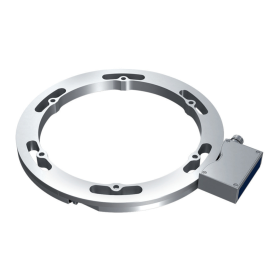
2.12) 2.10) 2.7) 2202, 2206 2.2) 2.6) 2.8) 2.3) 2.4) Parts of the 2.9) 2.11) products Produktteile 产品部件 2.1) 2.5) 2302, 2306 2.13) 2.16) 2.17) 2.14) 2.15) - Page 10 Scanning head Flange mount ClampFit 2.1 Scanning head 2.7 Ring segment 2.13 Ring segment 2.2 Mounting holes 2.8 Magnetic tape 2.14 Magnetic tape 2.3 LED indication, 2.9 Tethers 2.15 Tethers Power 2.10 Segment mounting 2.16 Segment mounting 2.4 LED indication, holes holes scanning...
-
Page 11: Risk Of Damage To The Product
3.1) 3.2) Risk of damage to the product Beschädigungs- gefahr 3.3) 3.4) 产品损坏风险 3.5) 3.6) 3.7) 3.8) - Page 12 The product is a precision measuring instrument. It should be handled with care, by experienced person- nel. The warnings below apply in the event of effects outside the limit values stated in the product’s data sheet. The product may be damaged 3.1 by ESD discharges if the electronics are touched 3.2 if the shaft is exposed to high mechanical forces 3.3 by moisture or chemical fluids (do not install...
-
Page 13: Flange And Clampfit Mount
Flange mount Fixing with axial screws Flanschmontage Befestigung mit Axialschrauben 法兰安装 用轴向螺钉固定... - Page 14 Flange mounting procedure: Step 1. Check that the dimensions of the mating shaft match the specification in the encoder data sheet. Step 2. Mount the ring segments together with included M6 screws and washers with a torque of 7 Nm. Step 3.
- Page 15 ClampFit mount Friction fitting to shaft ClampFit-Montage Kraftschlüssige Verbindung mit der Welle ClampFit 安装 轴上摩擦力...
- Page 16 ClampFit mounting procedure: Step 1. Make sure the surface where the encoder will be mounted is clean from any grease or dirt. Step 2. Check that the dimensions of the mating shaft match the specification in the encoder data sheet. Step 3.
-
Page 17: Scanning Head Mounting
Align the scanning head Abnehmer ausrichten 对齐扫描头 Tolerance for angle displace- ment Winkelversatz- toleranz 角度位移容许公 差... - Page 18 When mounting the scanning head, center the mark for alignment on the top of the head with the signal centre of the magnetic tape on the ring. Maximum axial displacement is ± 4 mm. Bei der Montage des Abnehmers die Ausrichtungs- markierung oben am Abnehmer zentriert zum Sig- nalzentrum des Magnetbands am Ring ausrichten.
- Page 19 Adjust the gap Luftspalt anpassen 调整间隙 Mount the scanning head Abnehmer montieren 安装扫描头...
- Page 20 Use the included distance tool to make sure that the correct gap between scanning head and ring is met: • MRI 2XX6 Air gap 0.1-6 mm (Nominal 3 mm) • MRI 2XX2 Air gap 0.1-3 mm (Nominal 1 mm) Mit Hilfe des mitgelieferten Abstandhalters sicher- stellen, dass der Abstand zwischen Abnehmer und Ring korrekt ist: •...
-
Page 21: Check Points For Mechanical Mounting
Check points for mechanical mounting Kontrollpunkte bei mechanischer Montage 机械安装检查要 点... - Page 22 Check the radial runout by slowly rotating the com- plete assembly. The gap between ring and scanning head should be inside the permitted tolerance in full circle (see chapter 5.2). The LED marked “SCANNING” on the scanning head will be lit with fixed green light when the gap is within the tolerance.
-
Page 23: Check Points For Electrical Mounting
7.1) Check points for electrical mounting 7.2) Kontrollpunkte bei elektrischer Montage L < Lmax 电气安装检查要 > 200 mm > 100 mm > 100 mm 点 7.3) R > 100 mm R > 40 mm 7.4) - Page 24 7.1 Use a shielded twisted-pair cable. The shielding must be connected to the chassis at both ends and be earthed at one point. 7.2 Keep potential sources of disturbance at the rec- ommended distance from the cable. Make sure that the length of the cable does not exceed the value specified in the product data sheet.
-
Page 25: Accessories
Accessories Zubehör 附件... - Page 26 Extra scanning head If additional scanning head is used, place the heads 180 degrees from each other. Zusätzlicher Abnehmer Bei Einsatz eines zusätzlichen Abnehmers ist dieser im Verhältnis zum ersten Abnehmer um 180 Grad versetzt anzubringen. 额外的扫描头 如果使用额外的扫描头,将扫描头彼此隔 度 放置。 Accessories from Leine &...
-
Page 27: Certificates And Approvals
9.1) Certificates and approvals 9.2) Zertifikate und Zulassungen Leine & Linde products conform to several standards and approvals. Certificates and documentation may 执照和认证标准 be provided upon request to your local Leine & Linde representative. 9.1 UL/CSA standards, type approval Most Leine & Linde products have been type tested in accordance with IEC 61010. - Page 28 Produkte von Leine & Linde erfüllen die Auflagen einer Reihe von Normen und Zulassungen. Auf Anfrage sind Zertifikate und Dokumentation beim Leine & Linde-Vertreter in Ihrer Nähe erhältlich. 9.1 Zulassung gemäß UL-/CSA-Normen Die meisten Produkte von Leine & Linde wurden gemäß...
- Page 29 Products from Leine & Linde are usually components in larger systems. These applications require the system as a whole to be tested, and do not depend on the component specifications only. Instructions in these mounting instructions apply to products from Leine & Linde, not for the system as a whole.
- Page 31 Monteringsanvisningar på ytterligare språk finns på www.leinelinde.se Hay instrucciones de montaje en otros idiomas en www.leinelinde.es Инструкции по установке на других языках приведе- ны на www.leinelinde.com...
- Page 32 MARCH 2018...
Need help?
Do you have a question about the MRI 2202 and is the answer not in the manual?
Questions and answers