Table of Contents
Advertisement
Quick Links
Advertisement
Table of Contents

Related Manuals for Roper Whitney 1016


Summary of Contents for Roper Whitney 1016
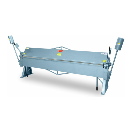
- Page 1 ROPER WHITNEY/CONNECTICUT FLOOR MODEL MANUAL BENDING BRAKES MODELS 816, 1018 AND 1016 INSTALLATION, OPERATION, AND MAINTENANCE MANUAL Version 2.1 ROPER WHITNEY 2833 HUFFMAN BLVD ROCKFORD, ILLINOIS 61103 OF ROCKFORD, INC. 815/962-3011 815/962-2227 FAX...
- Page 3 * Work support angle bar for full capacity 1-inch minimum flange * Positive rear material gauge adjustment * Improved leg design for lighter weight INSTALLATION, OPERATION, AND MAINTENANCE MANUAL Version 2.1 ROPER WHITNEY 2833 HUFFMAN BLVD ROCKFORD, ILLINOIS 61103 OF ROCKFORD, INC. 815/962-3011 815/962-2227 FAX Page i...
-
Page 4: About This Manual
Material in this manual is confidential, and Roper Whitney reserves all rights in this regard. If you have questions concerning usage or operating techniques not covered by... -
Page 5: Table Of Contents
Manual Brake Installation, Operation, and Maintenance Manual TABLE OF CONTENTS About This Manual Warranty Provisions Section 1: Safety Precautions General Precautions ........................... 1 Safety Precautions During Operation ....................2 Section 2: Machine Description Section 3: Specifications Section 4: Receiving and Installation Receiving ............................ - Page 6 Roper Whitney, at its option, will repair, replace, or refund the purchase price of any tool or machine which fails within the warranty period, and is found upon examination by Roper Whitney, to be defective in material or workmanship, or both.
-
Page 7: Section 1: Safety Precautions
Manual Brake Installation, Operation, and Maintenance Manual SECTION 1 SAFETY PRECAUTIONS Before using the Roper Whitney manual brake, carefully read and fully understand the safety precautions outlined in this section. pertain to GENERAL PRECAUTIONS the general workplace, and to the attitudes and work habits you bring to the job. -
Page 8: Safety Precautions During Operation
Manual Brake Installation, Operation, and Maintenance Manual SAFETY Do not attempt to operate the brake in excess of its rated capacity. Do not attempt to form wire, nails, rods or pipe on the machine. PRECAUTIONS DURING Avoid any pinch points created by movement of the machine's components. OPERATION Exercise care around the bending apron counterweights. -
Page 9: Section 2: Machine Description
Manual Brake Installation, Operation, and Maintenance Manual SECTION 2 MACHINE DESCRIPTION Roper Whitney floor mounted manual bending brakes are precision machines for use in bending mild steel and other sheet metals, including aluminum, brass, bronze, copper, duralumin; lead, monel metal, silver, carbon and stainless steel within rated capacity. -
Page 10: Section 3: Specifications
Manual Brake Installation, Operation, and Maintenance Manual SECTION 3 SPECIFICATIONS Feature Model Model Model 1016 1018 Bed Length 97 in. 121 in. 121 in. Capacity on mild steel, 1-in. flange With bending bar and angle in place 16 Ga. 16 Ga. 18 Ga. -
Page 11: Section 4: Receiving And Installation
Also check to see that all material listed on the bill of lading is present. Since Roper Whitney equipment is normally sold F.O.B., factory in Rockford, IL, our responsibility for transit damage ceases when the transportation company signs the bill of lading indicating it has received the items listed in good condition. -
Page 12: Site Preparation
Manual Brake Installation, Operation, and Maintenance Manual The clamping handles at each end of the brake are wrapped and wired in the down position to prevent damage and to prevent the handles from being used to move the brake. Remove the wires and wrapping. Wooden blocks are positioned between the upper and lower beam jaws to prevent damage during shipment. -
Page 13: Setting The Brake
Manual Brake Installation, Operation, and Maintenance Manual SETTING THE Using the overhead crane, lift the brake from the skid and place it in its desired location. Be sure the brake is properly balanced. BRAKE WARNING THE BRAKE TENDS TO BE TOPHEAVY AND CAN TWIST IN THE SLING Use care when moving the brake from the skid to avoid injury. -
Page 14: Installing The Counterweights
Manual Brake Installation, Operation, and Maintenance Manual INSTALLING THE Have an assistant raise the bending apron to the horizontal position, and hold it in that position while the counterweights are installed. COUNTER- WEIGHTS Install a counterweight in the mounting hole in each end of the bending apron. Adjust the counterweights so that they balance the bending aparon in the horizontal position. -
Page 15: Section 5: Setup
Manual Brake Installation, Operation, and Maintenance Manual SECTION 5 SETUP The machine has been adjusted and pretensioned at the factory. Set-up adjust- ments are for clamping pressure, material thickness, setting up for narrow or offset bends, setting bend angle control, and setting up of the optional rear material stops. SETTING Excessive clamping pressure is not required or desirable. -
Page 16: Adjusting For Material Thickness
Manual Brake Installation, Operation, and Maintenance Manual SETTING At each end of the machine, tighten upper toggle pin lock nut against the toggle anchor (see Figure 3). CLAMPING PRESSURE At each end of the machine, pull the clamping lever forward against the stop. -
Page 17: Setting Up For Narrow Or Offset Bends
Manual Brake Installation, Operation, and Maintenance Manual ADJUSTING FOR Move the upper beam forward or back until proper clearance is achieved by turning the thickness adjusting screw located at rear of the leg bracket MATERIAL on each end of the machine (see Figure 4). Final adjustment must always THICKNESS be toward the front of the brake to remove backlash from the adjusting screws. -
Page 18: Setting Up The Bend Angle Stop
Manual Brake Installation, Operation, and Maintenance Manual SETTING UP THE The bend angle stop can be adjusted for multiple or precision bends.Adjust the angle stop as follows: BEND ANGLE STOP Loosen the angle stop collar set screw and move the angle stop collar out toward the end of the angle stop rod. -
Page 19: Section 6: Operation
Manual Brake Installation, Operation, and Maintenance Manual SECTION 6 OPERATION GENERAL Operation of the brake is entirely manual, and the operator has full control of the operation at all times. INSTRUCTIONS Do not attempt to operate the brake in excess of its rated capacity. Do not attempt to form wire, nails, rods or pipe on the machine. -
Page 20: Bending The Material
Manual Brake Installation, Operation, and Maintenance Manual BENDING THE Bend the material to the desired bend angle using the apron lift handles to apply the bending force. Under no circumstances use the counterweight rods for MATERIAL leverage. If the material being bent is long and protrudes from the machine, lift it during the bending operation to avoid creases or crimps caused by material weight. -
Page 21: Hemming
Manual Brake Installation, Operation, and Maintenance Manual HEMMING Hemming is the most difficult operation to control accurately on a hand brake. Hemming creates pressure loads on the machine different than those created by regular bending, and optimum results will not be obtained using the same machine preloading for both hemming and bending. -
Page 22: Section 7: Periodic Maintenance
Manual Brake Installation, Operation, and Maintenance Manual SECTION 7 PERIODIC MAINTENANCE LUBRICATING Grease fittings are provided for rotating components where wear may occur. Use a medium weight bearing grease, such as SAE No. 30, and grease weekly when ..ROTATING the brake is being used. The rotating components are: the clamping lever assembly, COMPONENTS the apron hinge assembly (2 fittings), and the toggle pin bushing. -
Page 23: Adjusting The Clamping Collars
Manual Brake Installation, Operation, and Maintenance Manual ADJUSTING THE The retaining system used to hold the clamping levers in the open position require periodic adjustment. Adjust the collars using the following procedure: CLAMPING COLLARS STEEL FLAT WASHER CLAMPING LEVER (MODEL 1016 ONLY) CLAMPING COLLAR CLAMPING COLLAR... -
Page 24: Section 8: Maintenance Adjustments
Manual Brake Installation, Operation, and Maintenance Manual SECTION 8 MAINTENANCE ADJUSTMENTS BRAKE When the machine does not bend properly, it is sometimes necessary to readjust the crown on the beams. Use the following procedure: CROWNING ADJUSTMENTS Relieve all tension on the upper beam tensioning nuts and on the upper beam tensioning screw (see Figure 9). - Page 25 Manual Brake Installation, Operation, and Maintenance Manual BRAKE CROWNING ADJUSTMENTS TOGGLE ANCHOR LOWER TOGGLE PIN ADJUSTING NUT Figure 10. Upper Beam Clamp Adjusting Components. THE BEAM AND THE BED MUST BE IN CONTACT AT THE CENTER OF THE MACHINE BEAM EXAGGERATED VIEW OF GAP AT EACH END OF THE MACHINE THE GAP MUST BE EQUAL AT BOTH ENDS...
-
Page 26: Preloading Adjustment
Manual Brake Installation, Operation, and Maintenance Manual PRELOADING Once the brake crown has been set, the brake must be adjusted to produce straight bending and a uniform radius. Follow the procedure below: ADJUSTMENT Loosen the apron tensioning nuts on the apron, (see Figure 12) and the upper and lower beam tensioning nuts (see Figure 9). - Page 27 Manual Brake Installation, Operation, and Maintenance Manual PRELOADING Tighten lower beam tensioning nut until the edge of the bed is 1/64" above the top edge of the apron at the center (see Figure 9). The edges of ADJUSTMENT the bed and apron will then be parallel from end to end, with the edge of the bed 1/64"...
- Page 28 Manual Brake Installation, Operation, and Maintenance Manual Figure 14. Exploded View of Replacement Parts Page 22...
-
Page 29: Section 9: Repair Parts List
SECTION 9 REPAIR PARTS The table below identifies parts which may be replaced on the Roper Whitney manual bending brake. Parts may be ordered directly from your Roper Whitney distributor. If you have no distributor in your area, you may order the parts directly from the company. - Page 30 Manual Brake Installation, Operation, and Maintenance Manual Figure 15. Exploded View of Replacement Parts Page 24...
- Page 31 Manual Brake Installation, Operation, and Maintenance Manual ..continued from page 23 Part Number Ref. Model Model Model 1018 1016 Part Name Qty. 257020007 257020001 257020004 Beam 757080015 757080056 757080015 Bushing, Slide Pin 656164302 600164307 656164302 Ring, Retaining, Slide Pin Bushing 457080076 457080009 457080076...
- Page 32 For your higher production jobs, Roper Whitney of Rockford is pleased to offer..A A A A A utobr utobr utobr e 2000 e 2000 utobr ak ak e 2000 e 2000 utobr e 2000 Offered in a range of models from 4-feet to 13-feet, and capaci-...
Need help?
Do you have a question about the 1016 and is the answer not in the manual?
Questions and answers