Table of Contents
Advertisement
P H O T O V O LTA I C S Y S T E M C O N T R O L L E R S
O
PERATOR
Rated PV current
Rated Load current
System voltage:
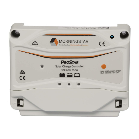
ProStar models
included in this
manual:
P
S
RO
RO
TAR
TAR
'
M
S
MODEL RATINGS
P
S
-12 P
S
RO
TAR
RO
12A
20A
8A
16A
12 and 24 volts, auto selected
• Standard
• With LCD meter
ANUAL
-20 P
S
-30
TAR
RO
TAR
30A
30A
Advertisement
Table of Contents

Related Manuals for Morningstar PROSTAR-12


Summary of Contents for Morningstar PROSTAR-12
- Page 1 P H O T O V O LTA I C S Y S T E M C O N T R O L L E R S ’ PERATOR ANUAL MODEL RATINGS -12 P -20 P Rated PV current Rated Load current System voltage: 12 and 24 volts, auto selected ProStar models...
-
Page 2: Table Of Contents
CONTENTS 1.0 G ............ 2 ENERAL NFORMATION 2.0 Q ..........3 UICK TART NSTRUCTIONS 3.0 I ..............4 NDICATORS 3.1 LED Indicators ..........4 3.2 Digital Meter & Disconnect ......5 4.0 I ..........6 NSTALLATION NSTRUCTIONS 4.1 Polarity Protection ..........6 4.2 Installation Procedure ........ -
Page 3: Quick Start Instructions
• Even though the system is only 12 or 24 volts, both the PV array and battery can contain lethal amounts of electrical power. • Do not splash water on the controller, do not allow water to enter the ventilation slots. •... -
Page 4: Indicators
3. Connect the BATTERY first. Observe that all LED’s flash in sequence one time. 4. Connect battery SENSE leads (if utilized). This is recom- mended if the controller is placed more than 2 to 3 meters from the battery. 5. Connect the PV (solar array). With sunlight, the green CHARGING LED will light in 2 minutes. -
Page 5: Digital Meter & Disconnect
BATTERY CHARGE Green ON: Battery near full charge BATTERY CHARGE Yellow ON: Battery at middle capacity (about 35% to 80% SOC) NOTE: does not indicate a problem BATTERY CHARGE FLASH: Battery at low charge, warning ON: Load has been disconnected All LED’s SEQUENTIAL FLASH: Load is short-circuited... -
Page 6: Installation Instructions
4.0 INSTALLATION INSTRUCTIONS LED I OLARITY ROTECTION NDICATIONS : Although the ProStar is fully protected from AUTION reversed polarity, the system operator and other equipment may be at risk when polarities are reversed. Carefully check each connection and observe the LED’s to make sure polarity is correct. LED I ONNECTION OLARITY... -
Page 7: Installation Procedure
4.2 I NSTALLATION ROCEDURE GENERAL INSTALLATION NOTES: • The ProStar prevents reverse current leakage at night, so a blocking diode is not required in the system. • The ProStar is designed to regulate ONLY PV power. Do NOT connect to any other type of power generator. •... - Page 8 Multiple ProStar units can be paralleled at the system battery, but be careful that no PV sub-array exceeds a controller’s individual current rating. 3. BATTERY (+ and -) Before connecting the battery, check the open-circuit voltage of the system battery. It must be at least 8 volts for the controller to operate.
- Page 9 CHARGING indicator comes on after 2 minutes to confirm that the PV array has been properly connected. 6. LOAD (+ and -) Turn the load off. Connect the load to LOAD terminals, and then turn the load on. If the battery is below the load disconnect voltage, the load will be discon- nected (normal LVD).
-
Page 10: Operation
5.0 OPERATION 5.1 C ONTROLLER PERATION The ProStar is a fully automatic PV system controller that includes many electronic functions to protect both the con- troller and the PV system. Battery charging is managed by a constant-voltage, PWM algorithm that has been optimized for PV systems. -
Page 11: Inspection And Maintenance
Automatic Safety • Load Short-Circuit: Instant load Disconnects disconnect. The LED’s flash in sequence. Battery must be disconnected to clear and reset (see section 4.2-6) • High Temperature: At very high tempera- tures, PV array first disconnected, then the load. The LED’s flash in sequence. Auto reconnect as temperature falls. -
Page 12: Troubleshooting
6. Inspect for dirt, insects, nests, and corrosion. 7. Check that the controller functions and LED indicators are correct for the system conditions at that time. 5.4 T ROUBLESHOOTING If something seems wrong with the PV system (for example, the load is not working or the battery is not charging), then it may be necessary to troubleshoot the controller. - Page 13 the battery. This will cause undercharging of the battery. See section 4.2-4. g. Check the condition of the battery. Determine if the battery voltage declines at night with no load. If unable to maintain its voltage, the battery may be failing. h.
- Page 14 d. If there is a problem with high voltage, the controller should go into the High Voltage Disconnect mode (see section 5.2). 3. L PERATING ROPERLY a. Check that the load is turned on. Check that no system fuses are defective. Check that no system circuit breakers are tripped.
-
Page 15: Specifications
5-year failure rates at a 90% confidence level • Dimensions: (inches) ... 6.01 (W) x 4.14 (H) x 2.17 (D) • ProStar-12 ........< 0.1% (mm) ....153 (W) x 105 (H) x 55 (D) • ProStar-20 ........< 0.1% •... - Page 16 P.O. B 20830 USA LNEY ARYLAND R1- APRIL 1996...
Need help?
Do you have a question about the PROSTAR-12 and is the answer not in the manual?
Questions and answers
When I turn my unit on the red and the orange light light up at the same time
When the red and orange LEDs are blinking together on the Morningstar PROSTAR-12, it indicates either a short circuit in the load or an overload condition.
This answer is automatically generated
What is wrong if a red light and a orange light are indicating at same time?
If both the red and orange (yellow) lights are on at the same time on the Morningstar PROSTAR-12, it indicates a load short circuit or overload condition.
This answer is automatically generated