Table of Contents
Advertisement
Advertisement
Table of Contents

Related Manuals for Morningstar SUNSAVER DUO


Summary of Contents for Morningstar SUNSAVER DUO
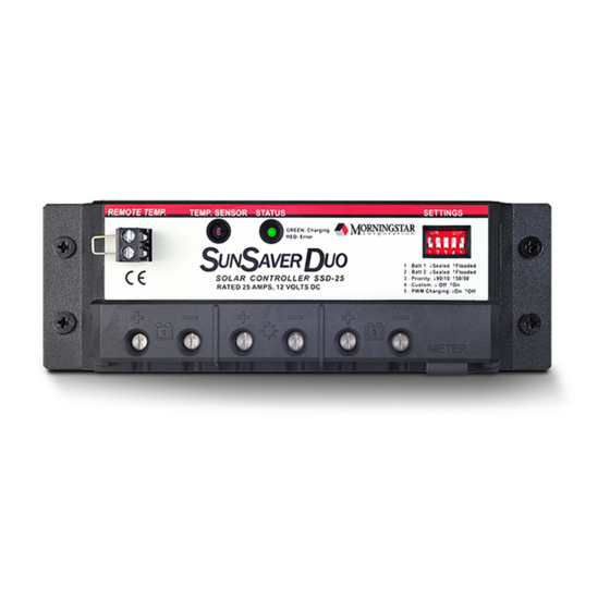
- Page 1 UNSAVER Installation and Operation Manual …. Dual Battery Charging Solar Controller for RVs, Caravans, and Boats …. Ratings ……………………………….………… Nominal Voltage 12 Volts Rated Solar Current 25 Amps www.morningstarcorp.com...
- Page 2 SUNSAVER DUO DIMENSIONS...
-
Page 3: Table Of Contents
Contents 1.0 Important Safety Information ................. 4 2.0 General Information ....................5 2.1 Overview ......................5 2.2 Morningstar Accessories ..................7 3.0 Installation ....................... 8 3.1 General Installation Notes ..................8 3.2 Adjusting DIP Switches ..................9 3.3 Mounting ......................11 3.4 Wiring ......................... -
Page 4: Important Safety Information
SunSaver Duo. Ensure that both batteries and the solar power have been disconnected before opening the access cover. There are no fuses or disconnects in the SunSaver Duo. Power must be removed externally. Do not allow water to enter the controller. -
Page 5: General Information
2.0 General Information 2.1 Overview Thank you for selecting the SunSaver Duo solar charge controller. The SunSaver Duo is an advanced PWM dual-battery charge controller for RV’s, caravans, boats, and other installations that require simultaneous battery charging of two separate (isolated) batteries. - Page 6 The major features of the SunSaver Duo are shown in figure 1 below. An explanation of each feature is provided. Remote Temperature Sensor (RTS) Terminals Local Temperature Settings Sensor Status LED DIP Switches Indicator RemoteMeter Battery #1 Solar Input Battery #2...
-
Page 7: Morningstar Accessories
Use when the ambient battery temperature differs from the ambient controller temperature by +/- 5 degrees C or more. An RTS can be attached to the SunSaver Duo at any time. The SunSaver Duo will automatically use the RTS for battery temperature compensation when installed. The standard cable length is 25 ft (7.6 m), and this can easily be extended to 100 ft (30 m) or longer. -
Page 8: Installation
Only charge lead-acid batteries. Each of the two SunSaver Duo Battery connections may be wired to one battery or a bank of batteries. The following instructions refer to a singular battery, but it shall be implied that each battery connection can be made to either one battery or a group of batteries wired in parallel to form a 12 volt battery bank. -
Page 9: Adjusting Dip Switches
Figure 2. Setting DIP switch definitions DIP Switches 1 & 2 – Battery Type Select The SunSaver Duo charges both sealed and flooded lead-acid batteries per the charging specifications in table 1 below. Sealed batteries are typically maintenance-free batteries that do not require water. Flooded batteries have removable caps that allow the addition of water when needed. - Page 10 DIP Switch 4 – Custom Setpoints If the standard battery type settings are not suitable, custom charging setpoints can be programmed using a PC and a Morningstar Serial to Meterbus adapter (not included). See Morningstar’s website for more information. DIP Switch 4 OFF: Factory settings (factory pre-set)
-
Page 11: Mounting
1. Locate the SunSaver Duo on a vertical surface protected from direct sun, high temperatures, and water. 2. Place the SunSaver Duo in the location where it will be mounted. Verify that there is sufficient room to run wires and that there is ample room above and below the controller for air flow. -
Page 12: Wiring
NOTE: Wiring charts on the back page of this manual provide minimum recommended wire size. NOTE: The SunSaver Duo can charge just 1 battery connected to either the Battery #1 or Battery #2 connections. If Battery #1 or Battery #2 is missing, the remaining battery will be charged with 100% of available power regardless of the charging priority setting. - Page 13 Confirm that the solar modules are wired for 12V nominal output before connecting them to the SunSaver Duo. In full sun, the output voltage of the solar modules should be 18 – 25 Volts before connection to the SunSaver Duo.
- Page 14 Upon connection of the Solar positive wire, the SunSaver Duo should begin the start-up sequence, flashing the Status LED 3 times. Step 5: Remote Temperature Sensor (optional) An optional Remote Temperature Sensor (purchased separately) measures the temperature directly at the battery for more accurate battery charging. Remove the wire jumper from the RTS terminals before installing the sensor.
- Page 15 NOTE: An existing common ground wire may connect the negative battery terminals of two or more on-board batteries. This cable will not interfere with the SunSaver Duo operation. NOTE: A wire jumper is installed across the Remote Temperature Sensor (RTS) terminals at the factory.
- Page 16 Connect the solar module(s) output to the Solar input connection of the SunSaver Duo. Multiple 12V nominal modules may be wired together in parallel and wired to the SunSaver Duo with one pair of wires. Use red wire for solar positive and black wire for solar negative.
- Page 17 Do not insert a fuse in the fuse holder at this time. Step 3: Battery #2 Connect Battery #2 to the SunSaver Duo as shown in figure 6. Use red wire for battery positive and black for battery negative. An in-line fuse holder should be wired in the positive line no further 12”...
- Page 18 Connect the solar module(s) output to the Solar input connection of the SunSaver Duo. Multiple 12V nominal modules may be wired together in parallel and wired to the SunSaver Duo with one pair of wires. Use appropriately sized red wire for solar positive and black wire for solar negative.
-
Page 19: Operation
4.0 Operation 4.1 LED Indications The Status LED indicates system operational state and any existing error conditions. Table 1 below defines the Status LED indications. Status LED Operating State Off : 5 second heartbeat¹ Night Green : on solid ( 5 second heartbeat² ) Bulk Charging Green : Flashing ³... -
Page 20: Charging Information
2. Absorption – PWM constant-voltage regulation to prevent heating and excessive battery gassing. Pulse charging to restore full battery capacity. 3. Float – After battery is fully charged, SunSaver Duo reduces to a float or “trickle charge”. 4. Boost (Flooded battery type only – Every 28 days) – A boost charge for flooded batteries, bringing uneven cell voltages into balance and extending battery life. -
Page 21: Protections
4.3 Protections Over-current – Solar charge current exceeds the current rating of the SunSaver Duo. Automatically reconnects in 30 seconds. CAUTION: A mis-wired connection of a battery to the Solar input when a second battery is already connected to a Battery input may damage the SunSaver Duo. -
Page 22: Inspection And Maintenance
4.4 Inspection and Maintenance The following inspections and maintenance tasks are recommended at least two times per year for best controller performance. Tighten all terminals. Inspect for loose, broken, or corroded connections. Verify all wire clamps and tie-downs are secure. ... -
Page 23: Troubleshooting
5.0 Troubleshooting 5.1 Error Indications NOTE: If an optional Morningstar Remote Meter is attached to the SunSaver Duo, use the self-diagnostic feature to determine the cause of the error indication. Refer to the Remote Meter Operator’s Manual for more information. - Page 24 Add a line filter such as a car audio alternator filter. If the noise still persists, adjust the Regulation Type DIP switch on the SunSaver Duo. See section 2.2 Configuring DIP Switches Problem: The SunSaver Duo reports E05 – removed RTS error. No RTS is connected.
-
Page 25: Limited Warranty
The SunSaver Duo charge controller is warranted to be free from defects in material and workmanship for a period of FIVE (5) years from the date of shipment to the original end user. Morningstar will, at its option, repair or replace any such defective products. -
Page 26: Technical Specifications
7.0 Technical Specifications Electrical Nominal system voltage 12 V Max. solar current 25 A Battery voltage range 1 V – 15 V Max. solar voltage 30 V Self-consumption 5.5 mA (night) 10.0 mA (charging) Accuracy Voltage 1.0 % Current... - Page 27 Mechanical Power terminals wire size (max.) Solid #6 AWG / 16 mm Multistrand #6 AWG / 16 mm Fine strand #8 AWG / 10 mm Terminal Diameter 0.210 in / 5.4 mm Power terminals torque (max.) 35 in-lb / 4 Nm ...
- Page 28 Solar Wire Gauge ( AWG ) Amps 3% Voltage drop, Annealed Copper Wire at 20°C One-way wire distance: Solar ↔ SunSaver Duo or SunSaver Duo ↔ Battery One Way Wire Distance ( meters ) Solar Wire Gauge ( mm^2 ) Amps 13.0...
Need help?
Do you have a question about the SUNSAVER DUO and is the answer not in the manual?
Questions and answers