Table of Contents
Advertisement
Quick Links
Advertisement
Table of Contents

Related Manuals for Siemens CPU 1518HF-4 PN


Summarization of Contents
Legal Information
Warning Notice System
Explains hazard levels and safety alert symbols used in the manual.
Qualified Personnel
Defines personnel qualified for system operation based on training and experience.
Proper Use of Siemens Products
Notes on correct usage, transport, storage, installation, and maintenance.
Trademarks
Lists registered trademarks of Siemens AG.
Disclaimer of Liability
Publisher's review and disclaimer for publication content.
Preface
Purpose of the Documentation
Explains manual's scope and supplements to system/function manuals.
Conventions
Defines terms like 'STEP 7' and notes for document interpretation.
Recycling and Disposal
Instructions for environmentally friendly recycling and disposal of old equipment.
Security Information
Information on industrial security functions and protection against cyber threats.
See Also
References to related online resources like Info Center and Industry Mall.
S7-1500R/H Documentation Guide
Basic Information
Covers configuration, installation, wiring, commissioning, and STEP 7 support.
Device Information
Describes module-specific information like properties and wiring diagrams.
General Information
Details general topics such as diagnostics and communication for the system.
S7-1500/ET 200MP Manual Collection
Refers to a collection of documentation for the redundant system.
SIMATIC S7-1500 Comparison List for Programming Languages
Provides an overview of instructions and functions for controller families.
"mySupport"
Describes the personal workspace for Industry Online Support.
Application Examples
Offers tools and examples for automation tasks and component interplay.
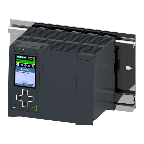
Product Overview
Configuration and Operating Principle
Details the components of the S7-1500H redundant system.
Configuration and Operating Principle
Explains mounting, connection of CPUs, and PROFINET ring setup.
Note: Standard Rail Adapter
Information on mounting the CPUs using a standard rail adapter.
Configuration and Operating Principle
Describes the principle of operation for primary and backup CPUs.
Additional Information
Points to the system manual for detailed operation and design.
Hardware Properties
Details hardware properties and identifies the module.
Note: Protective Film
Advises about a removable protective film on the display.
Properties
Details properties like CPU display and supply voltage.
PROFINET IO Interface (X1 P1 R and X1 P2 R)
Describes the 2-port PROFINET IO interface and its functionality.
PROFINET Interface (X2 P1 and X3 P1)
Details the single-port PROFINET interfaces X2 and X3.
H-Sync Interfaces (X4 P1 and X5 P1)
Explains the H-Sync interfaces for synchronization modules.
Synchronization Modules
Information on synchronization modules and their connection.
Fiber-Optic Cables
Notes on connecting synchronization modules with fiber-optic cables.
Operation of the CPUs as IO Controllers
How CPUs function as IO controllers for various IO devices.
Accessories
Points to the system manual for accessory information.
CPU Redundancy
Explains how two CPUs synchronize and switch over.
Safety Integrated
Describes processing of standard and safety programs, certifications.
Integrated System Diagnostics
How the system generates and outputs diagnostic messages.
Integrated Trace Functionality
Support for troubleshooting and optimizing programs using trace/logic analyzer.
PROFINET IO
Details PROFINET IO features like redundancy, RT, MRP, and PROFlenergy.
Integrated Technology
Details integrated closed-loop control functionality.
Security Integrated
Covers know-how, access, integrity, and password protection features.
Operator Controls and Display Elements
Shows the front view with LEDs, display, and control keys.
Note: Temperature Range for Display
Explains display behavior at different temperatures for service life.
Pulling and Plugging the Front Panel with Display
Instructions on removing and attaching the front panel during operation.
Locking the Front Panel
How to lock the front panel for security using seals or padlocks.
Reference
Points to system manual and display simulator for more info.
Front View of the CPU Without Front Flaps
Shows operator controls and connection elements without the front panel.
Rear View of the CPU
Illustrates connection elements on the rear of the CPU.
Bottom View
Shows the position of interfaces and synchronization modules on the underside.
Mode Selector
Explains how to use the mode selector for operating states.
Reference
Points to sections on operating states and the system manual.
Connecting
Terminal Assignment
Information on terminal assignment of interfaces and block diagram.
24 V DC Supply Voltage (X80)
Details the pin assignment for the 24 V DC supply voltage connector.
PROFINET Interface X1 with 2-Port Switch (X1 P1 R and X1 P2 R)
Explains the assignment of the 2-port PROFINET interface.
PROFINET Interface X2 with 1 Port (X2 P1) and X3 with Port (X3 P1)
Describes the single-port PROFINET interfaces X2 and X3.
H-Sync X4 Interface with 1 Port (X4 P1) and X5 with 1 Port (X5 P1)
Details the H-Sync interfaces for synchronization modules.
Additional Information
Points to system manual for connection and accessories.
Assignment of the MAC Addresses
Explains MAC address assignment for each CPU and its ports.
Distribution of the MAC Addresses of a CPU
Table showing assignment and labeling of MAC addresses.
Block Diagram
Presents the block diagram of the CPU 1518HF-4 PN.
Alarm, Error and System Messages
Status and Error Display of the CPU
Describes the LED displays for operating state and diagnostics.
LED Display
Shows the LED displays on the CPU 1518HF-4 PN.
LED Displays Depending on Operating States and System States
Illustrates operating states of primary/backup CPUs and system states.
Meaning of the RUN/STOP, ERROR and MAINT LEDs
Explains the meaning of the three main LEDs on the CPU.
Note: LED Patterns of the S7-1500H Redundant System
Notes on interpreting LED patterns and using diagnostic tools.
Meaning of the LEDs
Table detailing LED color combinations and their meanings.
Note: MAINT LED of the Two CPUs
Conditions under which the MAINT LEDs of both CPUs are off.
Note: LED Displays in Redundant Operating State
Notes that LED displays are identical in RUN-Redundant state.
Meaning of LINK RX/TX LED
Shows LED patterns for the LINK RX/TX status.
Note: "LED" Instruction
Information on using the "LED" instruction in STEP 7.
Technical Specifications
General Information
Product type, HW status, firmware version, product functions.
Display
Screen diagonal measurement of the CPU display.
Control Elements
Number of keys and type of mode selector switch.
Supply Voltage
Details on type, permissible ranges, and polarity protection.
Mains Buffering
Information on stored energy time for mains/voltage failures.
Input Current
Rated and max current consumption, inrush current.
Power
Infeed and consumption power for the backplane bus.
Power Loss
Typical power loss value for the CPU.
Memory
Number of memory card slots and requirement.
Work Memory
Specifies integrated memory for program and data.
Load Memory
Maximum load memory capacity for SIMATIC Memory Card.
Backup
Indicates if backup is maintenance-free.
CPU Processing Times
Typical processing times for various operations.
CPU-Blocks
Number of elements (OB, FB, FC, DB, UDTs) and their ranges.
DB
Number range and max size for Data Blocks.
FB
Number range and max size for Function Blocks.
FC
Number range and max size for Function Calls.
OB
Max size, number of various OB types (cyclic, alarm, startup).
Nesting Depth
Nesting depth per priority class for F-blocks.
Counters, Timers and Their Retentivity
Specifies the number and retentivity of S7 and IEC counters/timers.
Data Areas and Their Retentivity
Max retentive data area, flag size, clock memories, data blocks.
Local Data
Max local data per priority class.
Address Area
Number of IO modules and I/O address area sizes.
Subprocess Images
Max number of subprocess images.
Hardware Configuration
Number of distributed IO systems and IO controllers.
Time of Day
Clock type, backup time, and daily deviation.
Operating Hours Counter
Number of operating hours counted.
Clock Synchronization
Support for clock synchronization via NTP.
Number of PROFINET Interfaces
Specifies the total number of PROFINET interfaces.
1. Interface
Details on RJ45 (Ethernet) interface, ports, and switch.
Protocols
Supported protocols like IP, PROFINET IO, SIMATIC, Open IE.
PROFINET IO Controller Services
Services like PG/OP comms, Isochronous mode, IRT, PROFlenergy.
2. Interface
Details on the second RJ45 (Ethernet) interface.
3. Interface
Details on the third RJ45 (Ethernet) interface.
4. Interface
Information on plug-in interface modules (synchronization).
Interface Types
Details on RJ45 (Ethernet) for plug-in modules, speed, autonegotiation.
Protocols
Number of connections, reserved connections, routing paths.
Redundancy Mode
Details on Media redundancy, MRP, MRPD, switchover time.
SIMATIC Communication
PG/OP, S7 routing, S7 server/client communication.
Open IE Communication
Supported protocols like TCP/IP, ISO-on-TCP, UDP, DHCP, DNS, SNMP, DCP, LLDP.
Web Server
Availability of HTTP and HTTPS web server functionality.
OPC UA
Availability of OPC UA client and server.
Further Protocols
Support for MODBUS TCP.
Isochronous Mode
Equidistance setting for isochronous mode.
S7 Message Functions
Number of login stations, configurable/loadable/active program alarms.
Test Commissioning Functions
Support for joint commission, status block, single step, breakpoints.
Status/Control
Max variables for status/control and forcing.
Diagnostic Buffer
Presence, max entries, and powerfail-proof entries.
Traces
Number of configurable traces and memory size per trace.
Interrupts/Diagnostics/Status Information
Indicates if RUN/STOP, ERROR, MAINT LEDs and connection display are present.
Supported Technology Objects
Lists supported objects like Motion Control, PID controllers, counters.
Standards, Approvals, Certificates
Mentions suitability for safety functions.
Highest Safety Class Achievable in Safety Mode
Performance level (PLe) and SIL (SIL 3) ratings.
Probability of Failure
Failure probabilities for low demand and high demand modes.
Ambient Conditions
Ambient temperature limits for operation (horizontal/vertical).
Ambient Temperature During Storage/Transportation
Temperature limits for storage and transportation.
Altitude During Operation Relating to Sea Level
Restrictions for installation altitudes above sea level.
Programming Language
Supported programming languages (LAD, FBD, STL, SCL, GRAPH).
Know-How Protection
Details on user program, copy, and block protection.
Access Protection
Various levels of access protection (confidential data, write, read/write).
Cycle Time Monitoring
Lower and upper limits for cycle time monitoring.
Dimensions
Width, height, and depth of the CPU.
General Technical Specifications
Points to system manual for standards, approvals, EMC, protection class.
Dimension Drawing
Dimension Drawing
Contains dimension drawings of the module and front panel.
Dimension Drawings of the CPU 1518HF-4 PN
Shows front and side views with dimensions.
Dimension Drawing of the CPU 1518HF-4 PN, Side View with Front Panel Open
Shows side view with front panel open and dimensions.
Need help?
Do you have a question about the CPU 1518HF-4 PN and is the answer not in the manual?
Questions and answers