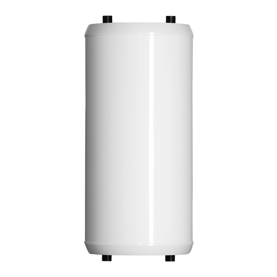
Summary of Contents for Nibe UKV 20-100
- Page 1 Installation and Operating Manual Installation and Operating Manual UKV 20-40 UKV 20-100 Buffer tanks 26.07.2017 26532...
- Page 2 Operation of the product by children is strictly prohibited. We reserve the right to make the product design changes and changes in the manual. ©NIBE 2017...
-
Page 3: Table Of Contents
3 Installation __________________6 Location of the Tank ______________________ 6 Installation Requirements __________________ 6 Installation of the Temperatur Sensor _________ 7 Installation of electric heating module ________ 8 Warnings and Practical Recommendations ____ 8 Buffer tanks Content | UKV 20-40, UKV 20-100... -
Page 4: General
1 General Introduction Thank you for your confi dence and choice of equip- ment by NIBE. To fully benefi t from the advantages of this product, please read this Manual before using it, and in particular chapters relating to the application, installation and maintenance, and warranty. -
Page 5: Design
Fig. 3 Section of the UKV 20-40 buffer tank Fig. 5 Upper view of the UKV 20-40 buffer tank Fig. 6 Upper view of the UKV 20-100 buffer tank DESCRIPTION: 1. -
Page 6: Installation
Buffer tanks Series UKV can be connected to open or NIBE is not responsible for fl ooding the room through closed central heating systems. Pressure in the C/H the safety valve. -
Page 7: Installation Of The Temperatur Sensor
4. Insert the sensor through the cover, and into the temperature sensor cover. (3) 5. Reinstall the enclosure cover together with ther- mal insulation. Buffer tanks Chapter 3 | Installation UKV 20-40, UKV 20-100... -
Page 8: Installation Of Electric Heating Module
Check fi lling of the C/H system from time to time. Type Tank ment power diameter MEL 1030 3 kW 1 ½” UKV 20-100 MEL 1060 6 kW 1 ½” WP-6.8 4,5 kW 1 ½” Chapter 3 | Installation Buffer tanks UKV 20-40, UKV 20-100... -
Page 9: Service
The purchased device consists in more than 90 % of parts that can be recycled and reused, so they are Fig. 12 Installation of the UKV 20-40 buffer tank in se- safe for the environment and human health. ries in order to increase the heating system capacity... -
Page 10: Technical Data
* Acc. to EU regulations No. 812/2013 & 814/2013. Dimensions ø temperature sensor cover 1” int. 1½” int. Fig. 14 Dimensions of the UKV 20-100 buffer tanks ø Fig. 15 Dimensions of the UKV 20-40 buffer tanks Chapter 6 | Technical Data Buffer tanks UKV 20-40, UKV 20-100... - Page 11 Notes: Buffer tanks UKV 20-40, UKV 20-100...
- Page 12 NIBE Energy Systems France Sarl, Zone industrielle RD 28, Rue du Pou du Ciel, 01600 Reyrieux Tel : 04 74 00 92 92 Fax : 04 74 00 42 00 E-mail: info@nibe.fr www.nibe.fr NIBE Energy Systems Ltd, 3C Broom Business Park, BridgeWay, Chesterfield S41 9QG Tel: 0845 095 1200 Fax: 0845 095 1201 E-mail: info@nibe.co.uk www.nibe.co.uk...


Need help?
Do you have a question about the UKV 20-100 and is the answer not in the manual?
Questions and answers