Sign In
Upload
Download
Table of Contents
Contents
Add to my manuals
Delete from my manuals
Share
URL of this page:
HTML Link:
Bookmark this page
Add
Manual will be automatically added to "My Manuals"
Print this page
×
Bookmark added
×
Added to my manuals
Manuals
Brands
Phoenix Contact Manuals
Measuring Instruments
EMpro EEM-MB371
User manual
Phoenix Contact EMpro EEM-MB371 User Manual
Multifunctional energy measuring devices for din rail mounting
Hide thumbs
1
2
3
4
5
6
7
8
9
10
11
12
13
14
15
16
17
18
19
20
21
22
23
24
25
26
27
28
29
30
31
32
33
34
35
36
37
38
39
40
41
42
43
44
45
46
47
48
49
50
51
52
53
54
55
56
57
58
59
60
61
62
63
64
65
66
67
68
69
70
71
72
73
74
75
76
77
78
79
80
81
82
83
84
85
86
87
88
89
90
91
92
93
94
95
96
97
98
99
100
101
102
103
104
105
106
107
108
109
110
111
112
113
114
115
116
117
118
119
120
121
122
123
124
125
126
127
128
129
130
131
132
133
134
135
136
137
138
139
140
141
142
143
144
145
146
147
148
149
150
151
152
153
154
155
156
157
158
159
160
161
162
163
164
165
166
167
168
169
170
171
172
173
174
175
176
177
178
179
180
181
182
183
184
185
186
187
188
189
190
191
192
193
194
195
196
197
198
page
of
198
Go
/
198
Contents
Table of Contents
Bookmarks
Table of Contents
Table of Contents
Eem-Mb-370-Pn
Table of Contents
1 For Your Safety
Identification of Warning Notes
Qualification of Users
Field of Application of the Product
Intended Use
Product Changes
Safety Notes
2 Device Description
Grid Type
Product Overview
3 Mounting and Installation
Mounting
Installation
Pin Assignment
Pin Assignment Example
Figure 11-4
Supply
Grid Types
One-Phase Network, Two Conductors, One Current Transformer
Two-Phase Network, Two Conductors, One Current Transformer
Three-Phase Network, Three Conductors, One Current Transform
Three-Phase Network, Three Conductors, Two Current Transform
Three-Phase Network, Three Conductors, Three Current Transform
Three-Phase Network, Four Conductors, One Current Transformer
Table 11-3
Three-Phase Network, Four Conductors, Three Current Transform
Two-Phase Network, Three Conductors, Two Current Transformers
Table 4-2
One-Phase Network, Two Conductors, One Rogowski Coil
Two-Phase Network, Two Conductors, One Rogowski Coil
Three-Phase Network, Three Conductors, One Rogowski Coil
Table 4-1
Table 11-2
Three-Phase Network, Three Conductors, Three Rogowski Coils
Three-Phase Network, Four Conductors, One Rogowski Coil
Three-Phase Network, Four Conductors, Three Rogowski Coils
Two-Phase Network, Three Conductors, Two Rogowski Coils
4 Operating and Indication Elements
Energy Measuring Device with Display
Energy Measuring Device Without Display
Energy Measuring Device Without Display, with Additional PROFINET Interface
Eem-Mb-370
Energy Measuring Device Without Display, with Additional Ethernet/Ip Interface
Eem-Mb370-Eip
Technical Data of the Display
Displaying the Events
Operating Elements on the Display (Softkeys)
5 Basic Device Configuration
Basic Device Configuration Via the Display
Step 1: Language Selection
Step 2: Network Settings
Step 3: Ipv4
Step 4: Grid Type
Selection of Grid Type with Current Transformers
Selection of Grid Type with Rogowski Coils
Step 5A: Current Input (Energy Measuring Device with Current Transformer)
Current Input
Step 5B: Current Input (Energy Measuring Device with Rogowski Coil)
Step 6: Voltage Input
Step 7: Configuration Overview
Step 8: Setting a Personal PIN
Step 9: Activating the PIN
Basic Device Configuration Via the Web Server
Step 1: Network Settings
Step 2: Selecting the Grid Type
Step 3: Configuration of the Current Input (Current Transformer)
Step 3: Configuration of the Current Input (Rogowski Coil)
Step 4: Voltage Input
Optional: Voltage Transducer
Step 5: Configuration Overview
Configuration Overview
6 Navigation Structure and Display
Menu Structure on the Display
Menu Structure on the Web Server
7 Device Settings and Information
Selecting the Language
Language" Menu
Date and Time
Reading the Date and Time
Date / Time" Menu
Settings: "Date / Time
Setting the Date and Time Manually
Synchronizing the Date and Time with an SNTP Server
Menu: "Settings, Date / Time, Settings, "SNTP Server"" Mode
Time Zones
Summer Time Rule
Menu: "Settings, Date / Time, Settings, Summer Time Rule
Adjusting the Display (Contract, Brightness, Illumination Time of Backlight)
Adjusting the Contrast of the Display
Settings: "Display, Contrast
Adjusting the Brightness of the Display
Figure 7-11 Settings: "Display, Brightness
Adjusting the Illumination Time of the Backlight
Figure 7-12 Menu: "Display, Permanent Light
Figure 7-13 Settings: "Display, Permanent Light
Figure 7-14: Settings: "Illumination Time
Selecting the Format of the Standard Display (IEC or IEEE)
Figure 7-15 Menu: "Display, Standard Display
Figure 7-16 Settings: "Display, Standard Display
Activating Color Change for Alarm
Figure 7-17 Menu: "Display, Alarm Light
Figure 7-18 Settings: "Display, Alarm Light
Selecting the Refresh Time for Displaying Measured Values
Figure 7-19 Menu: "Display, Refresh Time
Figure 7-20 Settings: "Display, Refresh Time
Adjusting the Display Via the Web Server
Figure 7-21: Web Server: "Settings, Display
Device Information
Figure 7-22 Menu: "Device Info
Figure 7-23 Display: "Device Info
Resetting the Device to Default Settings
Figure 7-24 Menu: "System, Factory Reset
Figure 7-25 Menu: "System, Factory Reset
Figure 0-1: Settings: "Illumination Time
8 Configuration
Access and Passwords
Editing Access Data Via the Display
Figure 8-1: Menu: "System, PIN XXXX
Figure 8-2: Settings: "System, PIN XXXX
Editing Access Data Via the Web Server
Figure 8-3: Menu: "System, User Management, Change Password
Deactivating the Configuration Via the Display
Figure 8-4: Menu: "Settings, Display
Deactivating the Modbus Communication Interface
Figure 8-5 Menu: "System, PIN Active/Wbm Active
Figure 8-6 Setting: "System, WBM Active
Figure 8-7 Setting: "System, PIN Active
Transferring Configuration Data
Exporting Configuration Data
Figure 8-8: Menu: "System, Configuration Data, Export Configuration
Importing Configuration Data
Figure 8-9: Menu: "System, Configuration Data, Import Configuration
Direct Transfer of Configuration Data
Figure 8-10 Menu: "System, Configuration Data, Transfer Configuration
9 Measuring Technology
Meter Readings
Figure 9-1: Menu: "Home, Meter Readings
Energy Meters
Figure 9-2 Menu: "E, Energy Total
Figure 9-3 Menu: "E, Energy Total
Energy Resettable
Figure 9-4: Menu: "E, Energy Resettable
Figure 9-5: Menu: "E, Energy Resettable
Tariff Meter
Figure 9-6: Menu: "Tar, Tariff Meter 1
Figure 9-7: Menu: "Tar, Tariff Meter 1
Operating Hours Counter
Figure 9-8 Menu: "Device Info, Operating Hours/Load Operation
Figure 9-9 Menu: "Device Info, Operating Hours/Load Operation
Statistics
Average Values
Figure 9-10: Menu: "Settings, Average Values
Figure 9-11 Menu: "Average Values, Settings
Figure 9-12 AVG over Fixed Interval (Fixed Block)
Figure 9-13 Sliding Average Value (Sliding Block)
Figure 9-14 Rolling Average Value (Rolling Block)
Figure 9-15: Prediction Calculation (Equally Weighted Average)
Figure 9-16: Prediction Generation (Weighted Average)
10 Functions
Digital Input
Figure 10-1 Digital Input
Impulse Counter
Figure 10-2: Menu: "Settings, Impulse Counter
Tariff Selection
Figure 10-3 Menu: "Settings, Tariffs, Digital Input
Synchronization of Average Values
Figure 10-4 Menu: "UL-L
Figure 10-5 Menu: "UL-L, UL-L Instantaneous" (Instantaneous Values, Instantaneous)
Figure 10-6 Menu: "UL-L, UL-L Min" (Min. Values, Min)
Figure 10-7 Menu: "UL-L, UL-L Max" (Max. Values, Max)
Figure 10-8 Menu: "UL-L, UL-L AVG Min" (Minimum Average Values, AVG Min)
Figure 10-9 Menu: "UL-L, UL-L AVG" (Average Values, AVG)
Figure 10-10 Menu: "UL-L, UL-L AVG Max" (Max. Average Values, AVG Max)
Acknowledgment of Alarms
Figure 10-11: Menu: "Settings, Average Values, Status
Digital Output
Figure 10-12: Menu: "Settings, Digital Output
Impulse
Figure 10-13 Menu: "Settings, Digital Output", "Impulse" Function
Device State
Figure 10-14: Menu: "Settings, Digital Output", "Device State" Function
Manually
Figure 10-15: Menu: "Settings, Digital Output", "Manually" Function
Alarm
Figure 10-16 Menu: "Settings, Digital Output", "Alarm" Function
Figure 10-17: Menu: "Settings, Alarm, Status
Figure 10-18: Menu: "Settings, Alarm
Rotary Field Direction
Figure 10-19 Menu: "Digital Output, Settings, "Rotary Field Direction
Deactivating the Digital Output
Figure 10-20: Menu: "Digital Output, Settings", "Deactivated" Function
Tariff Selection
Figure 10-21 Menu: "Tar, Tariff Meter
Figure 10-22: Menu: "Tar, Tariff Meter 1
Tariff Selection Via the Communication Interface
Figure 10-23: Menu: "Tariffs, Settings
Tariff Selection Using a Time Schedule
Figure 10-24: Menu: "Tariffs, Settings
Logic Gate
Figure 10-25 Menu: "Settings, Digital Output", "Alarm" Function
Figure 10-26: Logic Gate with and Operator
Figure 10-27: Logic Gate with NAND Operator
Figure 10-28 Logic Gate with or Operator
Figure 10-29 Logic Gate with nor Operator
Figure 10-30 Logic Gate with XOR Operator
Figure 10-31 Logic Gate with NXOR Operator
Data Logging
Figure 10-32 Menu: "Logging
Figure 10-33: "Menu: Logging, Settings
Figure 10-34 Menu: "Logging, Saved Data
Firmware Update
Execution
Figure 10-35 Execution of a Firmware Update
Figure 10-36 Progress and State
Security
11 Communication
Ethernet
IP Addressing
Configuration of the Communication Interface
Status of the Communication Interface
Security
Modbus
Function
Modbus/Rtu
Figure 11-5 Topology
Figure 11-6 Connections and Designations
Figure 11-7 Modbus Status
Figure 11-8 Modbus Settings
Modbus/Tcp
Modbus Gateway
Profinet
Software
Preparing the GSDML File
Integrating the GSDML File
Figure 11-9 "Options, Manage General Station Description Files (GSD)
Figure 11-1
Figure 11-10: Installing the Station Description File
Figure 11-11: Dialog: "Manage General Station Description Files
Integrating Hardware
Figure 11-12: "Devices & Networks" in the Network View
Figure 11-13: Selecting the Empro from the Hardware Catalog
Figure 11-14: Adding Empro to Network View
Figure 11-15: Empro in the Network View
Figure 11-16: Assigning an I/O Controller to the Empro
Figure 11-17: Selecting the I/O Controller
Figure 11-18: Networking Controller and Energy Measurement Device
Integrating Modules and Submodules
Figure 11-19: Adding a Module to the Device Overview
Figure 11-2
Figure 11-20: Submodules in the Hardware Catalog
Figure 11-21: Inserting Submodules
Figure 11-22: Available Modules and Submodules
Figure 11-23: Selecting a Submodule in the Device Overview
Linking Process Data
Assigning a Device Name
Function Check
Figure 11-3
Configuration
Modbus/Rtu
Modbus/Tcp
Modbus Gateway
Safety
Data Types and Registers
Register Table
Contents of the Register Table
Description of the Register Table
12 Technical Data
A Appendix For Document Lists
List of Figures
A 2 List of Tables
Index
Advertisement
Quick Links
Download this manual
EMpro - multifunctional energy measuring
devices for DIN rail mounting
User manual
Table of
Contents
Previous
Page
Next
Page
1
2
3
4
5
Advertisement
Chapters
Table of Contents
3
A Appendix For Document Lists
181
Table of Contents
Need help?
Do you have a question about the EMpro EEM-MB371 and is the answer not in the manual?
Ask a question
Questions and answers
Related Manuals for Phoenix Contact EMpro EEM-MB371
Measuring Instruments Phoenix Contact EMpro EEM-MA370 User Manual
Multifunctional energy measuring devices for din rail mounting (198 pages)
Measuring Instruments Phoenix Contact EEM-MA371 Installation Notes For Electricians
(8 pages)
Measuring Instruments Phoenix Contact EMpro EEM-MA371-R User Manual
Multifunctional energy measuring devices for din rail mounting (198 pages)
Measuring Instruments Phoenix Contact EMpro EEM-MB370 User Manual
Multifunctional energy measuring devices for din rail mounting (198 pages)
Measuring Instruments Phoenix Contact EMpro EEM-MA400 Installation Notes For Electrical Personnel
(148 pages)
Measuring Instruments Phoenix Contact EEM-MA200 User Manual
(75 pages)
Measuring Instruments Phoenix Contact EEM-MA250 User Manual
(75 pages)
Measuring Instruments Phoenix Contact EEM-EM157-EE User Manual
Mid energy meters (28 pages)
Measuring Instruments Phoenix Contact EEM-EM357-EE User Manual
Mid energy meters (32 pages)
Measuring Instruments Phoenix Contact TC MOBILE I/O Series User Manual
Remote monitoring via mobile network (70 pages)
Measuring Instruments Phoenix Contact SCK-C-MODBUS User Manual
Solarcheck string monitoring (116 pages)
Measuring Instruments Phoenix Contact LM-S User Manual
Lightning monitoring system (74 pages)
Measuring Instruments Phoenix Contact TC MOBILE I/O X200 User Manual
Remote monitoring via mobile network (62 pages)
Measuring Instruments Phoenix Contact TESTFOX CC Operating Manual
(76 pages)
Measuring Instruments Phoenix Contact Axioline F User Manual
Power measurement module (44 pages)
Summarization of Contents
For Your Safety
Safety Notes and User Qualification
Covers essential safety instructions, user qualifications, and product application fields.
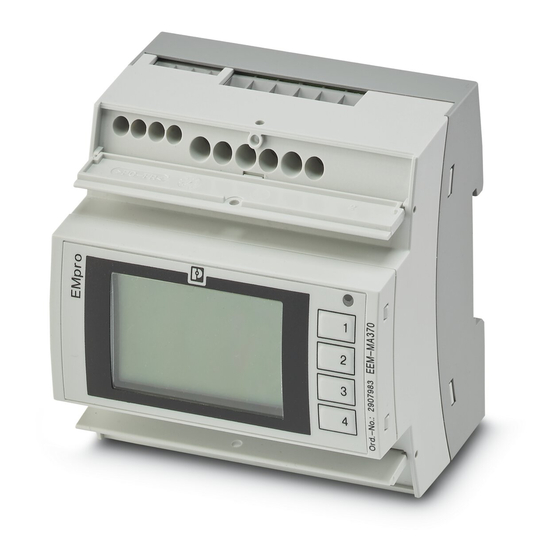
Device Description
Product Overview and Features
Introduces EMpro devices, their capabilities, advantages, and installation types.
Mounting and Installation
Installation Procedures and Grid Types
Details installation steps, pin assignments, supply connections, and supported grid types.
Operating and Indication Elements
Device Interfaces and Controls
Describes device displays, buttons, LEDs, and interface indicators for different models.
Basic Device Configuration
Configuration via Display
Guides through initial setup via display: language, network, grid, current/voltage input, and PIN.
Configuration via Web Server
Details initial configuration via web server: network, grid, current/voltage input, and overview.
Device Settings and Information
Language, Date, Time, and Display Settings
Covers language selection, date/time settings, and display adjustments (contrast, brightness).
Device Information and Reset
Explains how to retrieve device info and reset the device to factory default settings.
Configuration Management
Access Control and Data Transfer
Details password management, PIN settings, and transferring configuration data.
Measuring Technology
Meter Readings and Statistics
Explains meter readings (energy, hours) and statistical analysis like average values.
Functions
Digital Input and Output Operations
Covers digital input functions (pulse, tariff, sync, alarm ack) and digital output functions (impulse, state, alarm).
Tariff Selection and Logic Gates
Details tariff selection methods and using logic gates for alarm linking.
Firmware Update and Security
Guides through firmware updates, execution, and security considerations.
Communication Interfaces
Ethernet and Modbus Protocols
Covers Ethernet IP addressing, Modbus/RTU, Modbus/TCP, and gateway configurations.
PROFINET Integration and Data Handling
Details PROFINET integration, linking process data, and data types/registers.
Interface Safety and Register Table
Covers safety via PIN protection and accessing the register table for communication.
Technical Data
Table of Contents
Save PDF
Print
Rename the bookmark
Delete bookmark?
Delete from my manuals?
Login
Sign In
OR
Sign in with Facebook
Sign in with Google
Upload manual
Upload from disk
Upload from URL
Need help?
Do you have a question about the EMpro EEM-MB371 and is the answer not in the manual?
Questions and answers