Table of Contents

Related Manuals for Vanner TS12-2000


Summary of Contents for Vanner TS12-2000
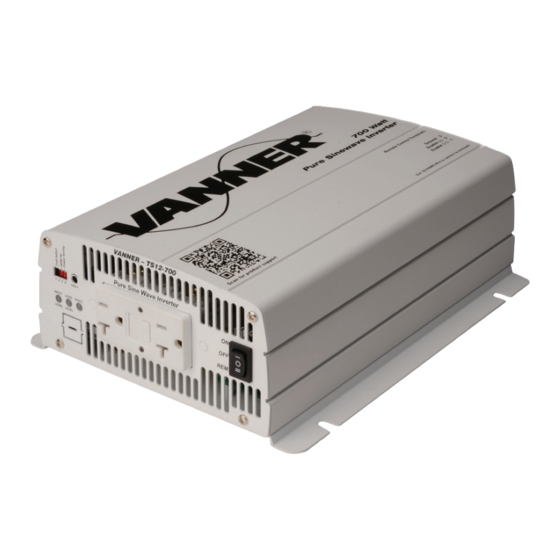
- Page 1 VANNER Owner’s Manual Incorporated TS Series 700 - 4000 Watt Pure Sine Wave Inverter Models TS12-700 TS24-700 TS12-1000 TS24-1000 TS12-1500 TS24-1500 TS12-2000 TS24-2000 TS12-3000 TS24-3000 TS24-4000 700~4000 Watt TS Series Inverter Owner’s Manual...
-
Page 2: Table Of Contents
3-1-5. AC output Interface ..............19 3-2. DC Input Side (Rear Panel) Introduction 3-2-2. Remote Control Black Terminal ........... 21 3-2-3. General instruction before DC Input ..........22 3-2-4. Chassis Ground ................22 3-3. Maintenance 700~4000 Watt TS Series Inverter Owner’s Manual... - Page 3 VANNER Owner’s Manual Incorporated OPERATION 4-1. Connection the DC cable 4-2. Connecting the input power 4-3. Connecting the loads 4-4. Switch ON Inverter 4-5. Protection Mechanism 700~4000 Watt TS Series Inverter Owner’s Manual...
-
Page 4: Safety Instructions
The following precautions should be taken when working on the inverter: Step 1 Remove watches, rings, or other metal objects Step 2 Use tools with insulated handles Step 3 Wear rubber gloves and boots 700~4000 Watt TS Series Inverter Owner’s Manual... -
Page 5: Other Safety Notes
1-2. Other Safety Notes Upon receipt, examine the carton box for damage. If you have found any damage on the carton box please notify Vanner. Do not operate near water or in excessive humidity. Do not open or disassemble the inverter, and warranty may be voided. -
Page 6: Functional Characteristics Introduction
Dry contact terminal Advanced Protection Features Input over/under voltage protection Internal over temperature protection Input reverse polarity protection (Fuse) Output overload protection Output short circuit protection 2-2. Block Diagram 700~4000 Watt TS Series Inverter Owner’s Manual... -
Page 7: Electrical Specification
Table 1. TS12-700/TS24-700 Specification. Note: : : : 1 Voltage range:Please refer to Figure 1 2 Normal load Condition : Vin =12.5V/25V/50V, Vo=100/110/115/120 VAC 80% Full load (PF=1.0) 3 Operating temperature:Please refer to Figure 2 700~4000 Watt TS Series Inverter Owner’s Manual... -
Page 8: Ts12-1000, Ts24-1000 Specification
Table 2. TS12-1000/TS24-1000 Specification. Note: : : : 1 Voltage range:Please refer to Figure 1 2 Normal load Condition : Vin =12.5V/25V/50V, Vo=100/110/115/120 VAC 80% Full load (PF=1.0) 3 Operating temperature:Please refer to Figure 2 700~4000 Watt TS Series Inverter Owner’s Manual... -
Page 9: Ts12-1500, Ts24-1500 Specification
Temperature & Load Controlled cooling Fan Table 3. TS12-1500/TS24-1500 Specification. Note: : : : 1 Voltage range:Please refer to Figure 1 2 Normal load Condition:Vin =12.5V/25V/50V, Vo=100/110/115/120VAC 80% Full load (PF=1.0) 3 Operating temperature:Please refer to Figure 2 700~4000 Watt TS Series Inverter Owner’s Manual... -
Page 10: Ts12-2000, Ts24-2000 Specification
4 Warning: : : : This is a class A product. In a domestic environment this product may cause radio interference in which case the user may be required to take adequate measures. -10- 700~4000 Watt TS Series Inverter Owner’s Manual... -
Page 11: Ts12-3000, Ts24-3000 Specification
4 Warning: : : : This is a class A product. In a domestic environment this product may cause radio interference in which case the user may be required to take adequate measures. -11- 700~4000 Watt TS Series Inverter Owner’s Manual... -
Page 12: Ts24-4000 Specification
4 Warning: : : : This is a class A product. In a domestic environment this product may cause radio interference in which case the user may be required to take adequate measures. -12- 700~4000 Watt TS Series Inverter Owner’s Manual... -
Page 13: Voltage & Temperature Performance
Figure 1. TS 700W~2000W Figure 2. TS 700W~2000W Output power vs. input Output power vs. temperature Figure 3. TS 3000W/4000W Figure 4. TS 3000W/4000W Output power vs. input Output power vs. temperature -13- 700~4000 Watt TS Series Inverter Owner’s Manual... -
Page 14: Mechanical Drawings
VANNER Owner’s Manual Incorporated 2-4. Mechanical Drawings Figure 5. TS series drawing (Top View) Figure 6. TS series drawing (AC output/Front View) Model A (inch) B (inch) C (inch) D (inch) E (inch) F (inch) TS 700W 12.35 1.46 7.72 8.27... -
Page 15: Installation And Maintenance
Figure 9. TS 300W/4000W AC output panel view Model TS Series Saving power adjustment Function switch Function LED Main switch AC output socket AC output terminal Table 8. TS Series AC output side introduction -15- 700~4000 Watt TS Series Inverter Owner’s Manual... -
Page 16: Main Switch
12.5V @ DC12V system Protection 25V @ DC24V system Red Blink (Input DC voltage under spec) Over Voltage 14.5V @ DC12V system Protection 29V @ DC24V system Red Fast Blink (Input DC voltage over spec) -16- 700~4000 Watt TS Series Inverter Owner’s Manual... -
Page 17: Function Switch Introduction
Table 12. Function Switch Definition 3-1-3-2. Output voltage selection (S1&S2) Output voltage 100V 110V 115V 120V Table 13. Function Switch definition: output voltage selection Note! 100V series can be selected between 100/110/115/120VAC -17- 700~4000 Watt TS Series Inverter Owner’s Manual... - Page 18 >160 W TS 1500W <110 W >160 W TS 2000W <110 W >160 W TS 3000W <240 W >280 W TS 4000W <240 W >280 W Table 17. Power saving setting range (Max) -18- 700~4000 Watt TS Series Inverter Owner’s Manual...
-
Page 19: Ac Output Interface
Applicable Model TS12-700, TS24-700 TS12-1000, TS24-1000 TS12-1500, TS24-1500 TS12-2000, TS24-2000 TS12-3000, TS24-3000 TS24-4000 Table 18. TS Series AC Socket vs. Model 3-1-5-2. TS Series 3000W/4000W AC output interface Terminal Wire color Wire length / gauge Line (L) Black Within 6 feet / AWG#... -
Page 20: Dc Input Side (Rear Panel) Introduction
Figure 13. TS 3000W/4000W DC input panel view Model TS Series ① Factory Port ② Remote control black terminal ③ Chassis ground ④ DC input connector Table 20. TS Series DC input side introduction -20- 700~4000 Watt TS Series Inverter Owner’s Manual... -
Page 21: Remote Control Black Terminal
“REMOTE” Use 18~ 24 #AWG wire to connect the remote control terminals ON:INV = ON ON:INV = ON OFF:INV = OFF OFF:INV = OFF BAT+ Figure 15. Wiring for control -21- 700~4000 Watt TS Series Inverter Owner’s Manual... -
Page 22: General Instruction Before Dc Input
TS24-4000 #1/0 ≧500A Table 22. TS Series Wiring Cable diameter and Inline Fuse Note! Batteries are capable of providing very large currents in case of short circuit. The fuse should be as close to the positive battery terminal as possible. -
Page 23: Maintenance
Do not use alcohol or ammonia based solutions. Regular service, and relocation of the inverter, should be performed by a qualified service technician. Avoid spilling liquid on the inverter. -23- 700~4000 Watt TS Series Inverter Owner’s Manual... - Page 24 / inverter and will void warranty. Also, only use high quality copper wire and keep the cable length short which is a maximum of 3 - 6 feet. Figure 16. Battery cabling -24- 700~4000 Watt TS Series Inverter Owner’s Manual...
- Page 25 33V ± 0.5V 29V ± 0.5V 21V± 0.5V 21V ± 0.5V 25V ± 0.5V Table 23. Protection Mechanism Over temperature protection Model Shutdown Restart 80°C 60°C Table 24. Over Temperature Protection Mechanism -25- 700~4000 Watt TS Series Inverter Owner’s Manual...
- Page 26 VANNER Owner’s Manual Incorporated Vanner Incorporated 4282 Reynolds Drive Hilliard, Ohio 43026 Ph: 800-AC POWER Ph: 614-771-2718 Fax: 614-771-4904 www.vanner.com Manual P/N: D917962-A June 2016 700~4000 Watt TS Series Inverter Owner’s Manual...
Need help?
Do you have a question about the TS12-2000 and is the answer not in the manual?
Questions and answers