Table of Contents
Advertisement
Instructions - Parts
™
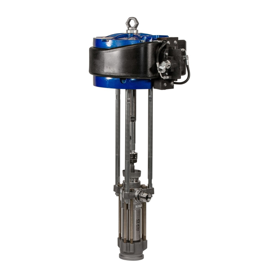
XL
10000 Air Motor
For use with high output reciprocating Graco pumps. For professional use only.
Important Safety Instructions
Read all warnings and instructions in this manual and in related
manuals. Save all instructions.
Model No. 24X856
100 psi (0.7 MPa, 7 bar) Maximum Working Pressure
Model No. 273088
100 psi (0.7 MPa, 7 bar) Maximum Working Pressure
(For use on XP-hf systems only)
334644C
EN
Advertisement
Table of Contents

Related Manuals for Graco 24X856


Summarization of Contents
Warnings
Equipment Misuse Hazard
General safety warnings regarding equipment misuse, potential for serious injury or death.
Moving Parts Hazard
Hazards associated with moving components, risk of pinching, cutting, or amputation.
Fire and Explosion Hazard
Warnings about flammable fumes, static sparking, ignition sources, and fire prevention in the work area.
Skin Injection Hazard
Risks of high-pressure fluid injection through skin, requiring immediate medical attention.
Personal Protective Equipment
Importance of wearing appropriate PPE like eyewear, hearing protection, respirators, and gloves.
General Information
Application
Details on the intended use and compatibility of the XL 10000 Air Motor with Graco pumps.
Reciprocating Signal Poppets
Information on the poppets used in the air valve, their accessibility, and interchangeability.
External Pilot Lines
Explanation of external pilot lines for cold weather operation and preventing signal blockage.
Manual Override Buttons
Functionality of manual override buttons for moving the shuttle valve, useful for ice or debris issues.
Low Pressure Operation
Specifications for operating the motor at low air pressures.
Performance
Description of the motor's performance characteristics, including pressure trace and output.
Minimum Icing
How oversized air handling parts reduce the effect of ice buildup on pump output.
Bleed Air
Use of the de-ice bleed air valve for warming air through the valve and exhaust.
Extended Capabilities
Compatibility with DataTrak counting, runaway stop solenoid, and linear position transducer.
Accessories
Bleed-type Master Air Valve
Requirement for relieving trapped air between the valve and motor.
Air Regulator
Necessary for adjusting air pressure to the motor and pump, requires a gauge.
Air Filter
Essential for removing dirt and moisture from compressed air supply, minimum 40 micron.
Air Lubrication
Recommendations for using an air line lubricator or adding oil to an air filter cup under specific conditions.
Troubleshooting
Ice In Air Motor
Explanation of ice formation in the air motor due to air expansion and methods to minimize it.
Repair
Preventive Maintenance Schedule
Establishing a maintenance schedule based on system operating conditions.
Pressure Relief Procedure
Critical steps to relieve system pressure before servicing to prevent injury.
Repair Air Valve
Replace Complete Air Valve
Steps for removing the old air valve and installing a new one.
Disassemble the Air Valve
Procedures for taking apart the air valve for inspection and repair.
Reassemble the Air Valve
Instructions for putting the air valve assembly back together after repair.
Repair Air Motor
Disconnect the Air Motor
Steps to safely disconnect the air motor from the pump and air supply lines.
Disassemble the Air Motor
Procedures for taking apart the air motor for inspection, cleaning, or part replacement.
Reassemble the Air Motor
Instructions for putting the air motor assembly back together after disassembly and repair.
Parts
Air Valve Parts
Detailed list and diagram of individual parts for the air valve assembly.
Kits and Accessories
Information on available repair kits and essential accessories for the air motor.
Dimensions (Model No. 24X856)
Mounting Hole Diagram
Illustration showing mounting hole patterns and dimensions for the 24X856 model.
Dimensions (Model No. 273088)
Mounting Hole Diagram
Illustration showing mounting hole patterns and dimensions for the 273088 model.
Need help?
Do you have a question about the 24X856 and is the answer not in the manual?
Questions and answers