Sign In
Upload
Download
Table of Contents
Contents
Add to my manuals
Delete from my manuals
Share
URL of this page:
HTML Link:
Bookmark this page
Add
Manual will be automatically added to "My Manuals"
Print this page
×
Bookmark added
×
Added to my manuals
Manuals
Brands
Kohler Manuals
Toilets
Veil K-5402R
Installation instructions manual
Kohler Veil K-5402R Installation Instructions Manual
Wall hung intelligent toilet
Hide thumbs
1
2
3
4
5
6
7
8
9
10
11
12
13
14
15
16
17
18
19
20
21
22
23
24
25
26
27
28
29
30
31
32
33
34
35
36
37
38
39
40
41
42
43
44
45
46
47
48
49
50
51
52
53
54
55
56
57
58
59
60
61
62
63
64
65
66
67
68
69
70
71
72
73
74
75
76
77
78
79
80
81
82
83
84
85
86
87
88
89
90
91
92
93
94
95
96
97
98
99
100
101
102
103
104
105
page
of
105
Go
/
105
Contents
Table of Contents
Troubleshooting
Bookmarks
Table of Contents
Before Installation
Dimension Drawing
Required Tools and Materials
Specification
Overall Diagram
Installation
Warning for Installation
In-Wall Tank Installation
Floor Discharge Installation Method
Side-To-Side Arrangement
Toilet Installation
Control Panel Installation
Top Button Installation
Dismantle and Service Discharge Valve
Clean Filter
Discharge Valve Adjustment
Water Inlet Valve Adjustment
Install Remote Control Docking Station
Troubleshooting
Customer Instructions
Advertisement
Quick Links
Download this manual
1247364-T01-B
Previous
Page
Next
Page
1
2
3
4
5
Advertisement
Table of Contents
Need help?
Do you have a question about the Veil K-5402R and is the answer not in the manual?
Ask a question
Questions and answers
Related Manuals for Kohler Veil K-5402R
Toilets Kohler VEIL K-5402A-0 Installation Instructions Manual
Wall hung intelligent toilet (26 pages)
Toilets Kohler K-8423A-0 Homeowner's Manual
Veil intelligent toilet (20 pages)
Toilets Kohler K-5402T-0 Homeowner's Manual
Veil intelligent toilet (85 pages)
Toilets Kohler K-5402 Homeowner's Manual
Wall-hung toilet with cleansing seat (45 pages)
Toilets Kohler Veil K-5402T Installation Instructions Manual
Wall hung intelligent toilet (105 pages)
Toilets Kohler Veil K-5402K Installation Instructions Manual
Wall hung intelligent toilet (105 pages)
Toilets Kohler K-5401 Homeowner's Manual
With bidet seat (56 pages)
Toilets Kohler K-5401 Installation Manual
Toilet with bidet seat (36 pages)
Toilets Kohler K-5401X Homeowner's Manual
Intelligent toilet (48 pages)
Toilets Kohler K-5401TW-2-0 Installation Manual
Veil+ intelligent toilet (29 pages)
Toilets Kohler K-5401TW-2-0 Homeowner's Manual
Veil+ intelligent toilet (45 pages)
Toilets Kohler K-5401IN-0 Installation Manual
Veil intelligent toilet (17 pages)
Toilets Kohler VEIL K-5401T Installation Manual
(61 pages)
Toilets Kohler Veil Comfort Height K-5401-0 Homeowner's Manual
Toilet with cleansing seat (49 pages)
Toilets Kohler Veil Comfort Height Homeowner's Manual
(61 pages)
Toilets Kohler VEIL K-5401T-3-0 Homeowner's Manual
Intelligent toilet (45 pages)
Summarization of Contents
Before Installation
A. Hold the edge of toilet bowl and slide out from packaging box.
Hold toilet bowl edge and slide out from packaging box.
WARNING: Risk of electric shock. Disconnect power before servicing.
Warning: Risk of electric shock. Disconnect power before any servicing.
WARNING: Risk of electric shock. For plug-in installations/wall-mounted electrical supply: Connect only to a properly-grounded, grounding-type circuit-interrupter (GFCI) or Residual Current Device (RCD) which is protected by a Ground-Fault Circuit-Interrupter (GFCI) or Earth Leakage Circuit-Breaker (ELCB).
Warning: Connect electrical supply only to GFCI/ELCB protected circuits for wall-mounted installations.
Required tools and materials
Dimension Drawing
Toilet dimension drawing
Installation
A. Remove old toilet (if there is one)
Step-by-step instructions for removing a pre-existing toilet.
B. Warning for installation
Critical warnings and safety precautions for the installation process.
C. In-wall tank installation
1. Remove in-wall tank from packing box, Tear paper board up inside water tank first, Then remove support paper board and plug under motor assembly.
Unpack and disassemble the in-wall tank, removing internal supports.
2. Loose hex-head screw and adjust mounting bracket height as shown in Fig.A.
Adjust mounting bracket height by loosening the hex-head screw.
A. Insert lag bolt anchor into the installation hole, then fasten mounting bracket by lag bolt. Adjust position and then insert the washer, tighten nut.
B. Insert lag bolt, then fasten supporting bracket by lag bolt. Adjust position and then insert the washer, tighten nut.
D. Floor discharge installation method
1. Loose knob to “OPEN” position on mounting bracket, then insert discharge pipe in mounting bracket, adjust position and tighten discharge pipe to “LOCK” position by screwdriver, At last, insert discharge pipe into discharge port.
Connect discharge pipe to bracket, adjust, and secure with knob and screwdriver.
2. Screw lag bolt in water tank hole as shown, then place big gasket on discharge port, small gasket on water inlet, Prepare the wall.
3. Connect tap water braided tube on the top of water tank for water supply as shown.
4. Place square cover within protection cover within water tank, then snap buckle into slot, tighten square cover bolts on water tank,
E. Side-to-side arrangement
1. Loose knob to “OPEN” position on mounting bracket, then insert discharge pipe in mounting bracket, Adjust position and tighten discharge pipe to “LOCK” position by screwdriver,
Connect discharge pipe to bracket via knob and screwdriver, adjusting position as needed.
F. Toilet installation
1. Remove left/right side panel
Remove the left and right side panels of the toilet.
3. Mark reserved space on rear end of discharge pipe and water inlet pipe, cut excessive part off. Then file the surface and chamfer the pipes.
4. Place big or small rubber seal on discharge pipe, water inlet, then insert on corresponding pipeline.
5. First, stick lag bolt washer against the wall as shown, then apply grease on discharge port and discharge hole so provide an easier installation.
6. First, place lag washer, rubber bushing, washer on lag bolt as shown, then tighten hex nut by ring spanner. Check toilet flatness by level. Then tighten hex-head nut.
7. Remove 2 cross head self-tapping screws on toilet right side, then dismantle power cord side panel, Then remove residual 3 cross head self-tapping screws, and then dismantle junction box cover,
8. Cross 3 power cord (hard cord) through rubber gasket from the wall, connect to junction box.
G. Control Panel Installation
1. First, slide water splash plate into slot A and B and insert in square cover slot.
Slide water splash plate into slots A and B on the square cover.
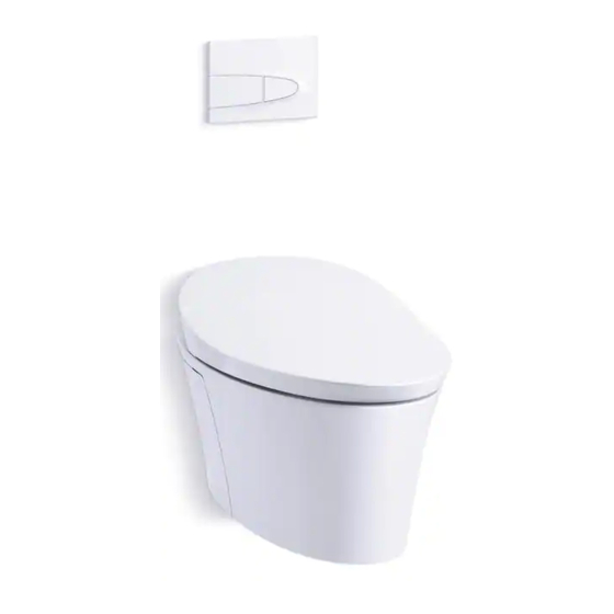
H. Top button Installation
1. When tighten four locknuts on supporting board, adjust to “OPEN” mark as shown.
Loosen locknuts on supporting board by aligning with 'OPEN' mark.
2. Tighten four screws to “LOCK” mark after installing supporting board as shown,
3. Screw two lag bolts into bracket as shown...
4. Align control panel lag washer with snap in position as shown, then push forward and fasten, Install motor assembly signal wire and control panel signal wire.
5. It is ready to use when connect to power and water supply after installation.
Dismantle and service discharge valve
1. Dismantle control panel bottom as shown, For dual hands push control panel bottom for upward pull out, Dismantle motor assembly signal wire and control panel signal wire.
Remove control panel bottom and disconnect wiring.
2. Unscrew two lag bolts as shown.
3. Pay special attention when dismantle supporting board 4 lock nuts, all bolts shall align with “OPEN” mark.
4. Dismantle supporting board as shown.
5. Pull water splash plate out.
6. Dismantle motor assembly snap-in mechanism, remove motor assembly.
7. Hold bracket top by hand as shown, then lift up to unlock the bracket.
8. Take discharge valve lever out from lag washers on both ends as shown.
9. Open/close water supply. Rotate valve switch to open/close water supply as shown.
10. Loose filter nut as shown, then take water inlet valve out.
11. Loose filter nut as shown, then take water inlet valve out for cleaning or adjusting.
12. Hold fastener by hand as shown, pull the top of fastener along the direction of arrow, Then remove fastener.
13. Rotate discharge valve along the arrow direction as shown to remove discharge valve.
14. Loosen discharge valve as shown and then take out valve for cleaning or adjusting.
I. Clean Filter
Loosen filter locknut as shown, clean filter dirt by water, then tighten locknut to original place.
Clean filter by loosening locknut, washing, and re-tightening.
J. Discharge valve adjustment
K. Water inlet valve adjustment
Install Remote Control Docking Station
Select a proper position for docking station installation. This position shall be easily operate by customer when seated.
Choose an accessible location for docking station for easy operation.
Public anti-theft installation method
Table of Contents
Print
Rename the bookmark
Delete bookmark?
Delete from my manuals?
Login
Sign In
OR
Sign in with Facebook
Sign in with Google
Upload manual
Upload from disk
Upload from URL
Need help?
Do you have a question about the Veil K-5402R and is the answer not in the manual?
Questions and answers