Table of Contents
Advertisement
—
A B B M E A S U R E M E N T & A N A LY T I C S | O P E R AT I N G I N S T R U C T I O N
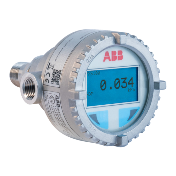
PGS100 and PAS100
Gauge and absolute pressure transmitters
Introduction
—
PGS100/PAS100 model
The present manual provides information on
installing, operating, troubleshooting the PGS and
PAS pressure transmitter models. Every section of
the present manual is specifically dedicated to the
specific phase of the transmitter lifecycle starting
from the receipt of the transmitter and its
identification, passing to the installation, to the
electrical connections, to the configuration and to
the troubleshooting and maintenance operations,
as applicable.
The pressure transmitters model PGS and PAS are
field mounted, microprocessor based electronic
transmitters. Accurate and reliable measurement of
gauge and absolute pressure is provided, in the even
most difficult and hazardous industrial
environments. These models can be configured to
provide specific industrial output signals according
to 4 to 20mA with HART digital communication.
Engineered solutions for all
applications
Measurement made easy
For more information
Further publications for PGS and PAS family of
pressure products are available for free download
from:
www.abb.com/measurement
or by scanning this code:
Download the
Brochure
or search for
RB/PGS/PAS100-EN on https://library.abb.com/en.
Advertisement
Table of Contents

Related Manuals for ABB PAS100


Summarization of Contents
1 Safety
General Safety Information
Overview of safety aspects, improper use, and technical limits for device operation.
Operational & Warranty Guidance
Manufacturer's liability, warranty provisions, and instructions for use.
1 Safety
Personnel and Device Handling
Operator liability, qualified personnel, returning devices, and transport/storage.
Lifecycle Safety and Electrical Installation
Disposal, WEEE guidelines, and electrical installation safety.
1 Safety
Inspection, Maintenance, and Security
Safety for inspection/maintenance, cyber security, and disclaimers.
Communication Protocol Specifics
Notes on HART protocol security and application assessment.
2 Transmitter overview
Transmitter Components Overview
Overview of the physical parts of the pressure transmitter.
Range and Span Considerations
Definitions and limitations for range and span settings.
3 Opening the box
Identification Plates
Details and purpose of various identification plates on the device.
Optional Wired-on Plate
Information about the optional custom-engraved stainless steel plate.
4 Mounting
General Mounting Instructions
General instructions and considerations before installing the transmitter.
4 Mounting
IP Protection and Designation
Explanation of IP ratings and their meaning for housing protection.
Hazardous Area and PED Compliance
Requirements for hazardous areas and Pressure Equipment Directive.
4 Mounting
P Style Transmitter Mounting
Specific mounting instructions for P style transmitters.
Sealing, Connections, and Moisture Protection
Guidelines for sealing, connections, and preventing moisture ingress.
4 Mounting
Measuring Pipe Installation
Correct installation and layout guidelines for measuring pipes.
5 Transmitter wiring
Supply Requirements and Wire Specifications
Wire gauge, shielding, grounding, and power supply needs.
Cable Connection Details
Details on electrical connection ports and cable preparation.
5 Transmitter wiring
Wiring Procedure and Grounding
Step-by-step wiring, sealing ports, and grounding the housing.
5 Transmitter wiring
HART Output Wiring and Communication Setup
Wiring for HART output and setting up PC communication.
6 Commissioning
General Remarks and Output Signals
Pre-operation checks, starting procedures, and output signal behavior.
Zero/Span and Write Protection
Adjusting zero/span and enabling/disabling write protection.
6 Commissioning
Local Display Features
Features and visualization of the LCD dot matrix display.
6 Commissioning
Adjusting Range Values and Sensors
Correcting zero shifts and adjusting LRV/URV via buttons or display.
6 Commissioning
LCD Display Installation and Removal
Step-by-step guide for LCD display installation and removal.
6 Commissioning
Pressure Sensor Ventilation
Importance of the ventilation port and avoiding obstruction for PGS100.
7 Operation (only HART version)
Display Navigation and Diagnostics
Navigating LCD, local diagnostic menu, and error messages.
Easy Setup Menu Structure
Overview of the Easy Setup menu and its steps.
7 Operation
Easy Setup Menu Flow
Visual flow of the Easy Setup menu for configuration.
8 Error messages
LCD Display Error Messages
Icons and text for error/fault messages on the LCD.
Error States and Alarms
Table of error codes, descriptions, causes, and suggested actions.
8 Error messages
QR Code Digital Advanced Diagnostics
Using QR codes for advanced diagnostics and information retrieval.
QR Code Channel Partner Support
Using QR codes for accessing ABB channel partner contact information.
9 Maintenance / Repair
Maintenance and General Checks
General maintenance, cleaning, and checks for wear and leaks.
Returns and Removal Procedures
Procedures for sending defective transmitters for repair.
10 Hazardous Area considerations
Specific Use Conditions and Explosion Protection
Special use conditions, explosion protection directives, and intrinsic safety.
Combustible Dust and Area Classification
Installation for combustible dust areas and general hazardous area classification.
10 Hazardous Area considerations
Hazardous Atmospheres: ATEX and IECEx
ATEX and IECEx protection types, temperatures, and power supply limits.
10 Hazardous Area considerations
Canadian Standards Association (US & Canada)
US & Canadian CSA markings, temperature limits, and power supply requirements.
Need help?
Do you have a question about the PAS100 and is the answer not in the manual?
Questions and answers