Table of Contents
Advertisement
Quick Links
Advertisement
Table of Contents

Related Manuals for Falcon E9342


Summary of Contents for Falcon E9342
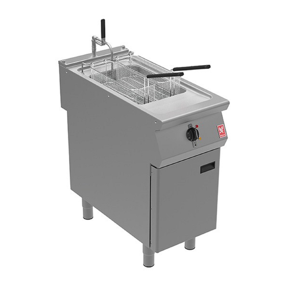
- Page 1 F900 SERIES User, installation and servicing instructions ELECTRIC TWIN WELL FRYER E9342/E9342B2/E9342F/E9342F2 Read these instructions before use DATE PURCHASED: MODEL NUMBER: SERIAL NUMBER: DEALER: SERVICE PROVIDER: T100968 Rev No: 8 Published: 20/11/2018...
- Page 2 Dear Customer Thank you for choosing Falcon Foodservice Equipment. This manual can be downloaded from www.falconfoodservice.com or scan here: IMPORTANT: Please keep this manual for future reference. Falcon Foodservice Equipment HEAD OFFICE Wallace View, Hillfoots Road, Stirling. FK9 5PY. Scotland.
- Page 3 SYMBOLS SCREWDRIVER SPANNER COOKING OIL GREASE WARNING SPARK IGNITION FLAME VIEWPORT ALLEN KEY IGNITER C SPANNER REMOVE DEVICE...
- Page 4 We recommend supplementary electrical protection with the use of a residual current device (RCD). The appliance has been designed and approved to use Falcon kick plates; non Falcon kick plates could potentially adversely affect the performance of the appliance by restricting the air to the appliance.
-
Page 5: Table Of Contents
CONTENTS APPLIANCE INFORMATION ..................7 OPERATION ......................8 COMPONENT PARTS .................... 8 CONTROLS ......................10 USING THE FRYER – NORMAL OPERATION ............ 11 USING THE FRYER – ECO MODE ..............13 USING THE FRYER – FAT MELT ................ 13 FILTRATION ......................14 CLEANING AND MAINTENANCE ................ - Page 6 7.12 CIRCUIT DIAGRAMS ..................36 7.13 WIRING DIAGRAMS ..................39 ACCESSORIES ....................... 42 SPLASHGUARD ....................42 OIL RETURN HOSE ..................... 42 FAULT FINDING ...................... 43 10.0 SPARE PARTS ......................44 11.0 SERVICE INFORMATION ..................45...
-
Page 7: Appliance Information
1.0 APPLIANCE INFORMATION This appliance has been CE-marked on the basis of compliance with the relevant EU directives for the heat inputs, gas pressures and voltages stated on the data plate. A - Serial No B - Model No C - Flue Type D - Gas Category E - Gas Pressure F - Gas Type... -
Page 8: Operation
2.0 OPERATION 2.1 COMPONENT PARTS E9342F: E9342F2: Dust cover Basket Hanger Baskets (2 Off) Element Fry plate (2 Off) Filtration Basket and Mesh Filter (E9342/F Only) Drain Prod /Lifting / Scraping tool Large Single Bucket (E9342/F Only) Oil Return Pipe (E9342F/F2 Only) Filtration Basket and Mesh Filter (E9342F2 Only) Element Turn Key Small Oil Bucket (E9342F2 Only) - Page 9 Quick Release Connection (E9342F/F2 Only) Mode Control Switch LH Temperature Control Filtration Pump Switch (E9342F/F2 Only) RH Temperature Control Heat Demand Neon (Amber) Safety Thermostat Reset Power Neon (Red) Drain Valve Lock Pin Micro Switch Neon (Amber) Drain valve Element Turn Cover Cap...
-
Page 10: Controls
2.2 CONTROLS Temperature Control OFF Position Element ON Temperature Control Minimum Mark Element OFF Drain Valve Closed Position Filtration Pump ON (E9342F/F2 Only) Element Turn Key Filtration Pump OFF (E9342F/F2 Only) ECO/FAT MELT Mode... -
Page 11: Using The Fryer - Normal Operation
2.3 USING THE FRYER – NORMAL OPERATION 2.3.1 Before use, clean the appliance inside and out. See section 3.0. 2.3.2 Ensure each drain valve is closed. Fill each pan with cold cooking medium to -MIN- (cold fill) mark as shown below. Once cooking medium is hot, it will expand and reach the –MAX- (hot oil) mark. - Page 12 2.3.6 For optimum cooking performance, use the recommended load and temperature settings shown in the table below: Food Product Maximum Kg / Half Basket Optimum Oil Temperature Pre-blanched chilled fries 0.75* Frozen fries 0.75* * This equates to roughly filling the basket 1/2 way up. OVERLOADING THE BASKETS WILL AFFECT THE FRYER PERFORMANCE.
-
Page 13: Using The Fryer - Eco Mode
g) If the safety thermostat reactivates call a qualified technician to carry out an investigation. 2.3.8 To switch appliance off, turn both Temperature Control Knobs to “Off Position” and turn both Mode Control Knobs to “Element Off”. 2.4 USING THE FRYER – ECO MODE Use ECO mode for pre-heating. -
Page 14: Filtration
2.6 FILTRATION 2.6.1 Ensure the Heating Elements are turned off. 2.6.2 Wait 15/20 minutes to allow oil to cool. 2.6.3 Ensure Filtration Basket & Mesh Filter are clean and dry and locate them in the Oil Bucket. 2.6.4 Ensure Oil Bucket is clean and dry. Place it on the Runner Cradle and slide it back into the appliance until it engages with the pump. -
Page 15: Cleaning And Maintenance
2.6.13 To remove the Oil Return Pipe, pull down on the Quick Release Connection and pull off the Oil Return Pipe as shown below. 3.0 CLEANING AND MAINTENANCE BEFORE ANY CLEANING IS UNDERTAKEN, ISOLATE APPLIANCE FROM MAINS POWER SUPPLY AT ISOLATOR SWITCH. SUITABLE PROTECTIVE CLOTHING MUST BE WORN WHEN CLEANING THIS APPLIANCE. -
Page 16: Cleaning And Maintenance
3.1 CLEANING AND MAINTENANCE 3.1.1 Switch appliance off and cool down. 3.1.2 Ensure Filtration Basket & Mesh Filter are located in the Oil Bucket. Place Oil Bucket on the Runner Cradle and slide it back into the appliance until it engages with the pump. - Page 17 3.1.6 Attach the Oil Return Pipe and switch on the filtration pump. Move Oil Return Pipe from side to side to wash away debris (see section 2.6.13). 3.1.7 Use the scraping end (A) of the Drain Prod / Lifting / Scraping Tool as shown below to scrape any debris in the pan down the drain.
- Page 18 3.1.8 It is recommended to use the accessory hose (see section 8.2) and switch on the filtration pump to flush out the excess debris from hard to reach places. 3.1.9 After filtering wait 30 seconds before removing bucket. 3.1.10 Remove Oil Bucket by pulling it forward then lifting it upwards by the wire handle as shown below.
-
Page 19: Specification
3.1.18 Open Drain Valve to empty water into Oil Bucket. 3.1.19 Rinse pan and dry thoroughly. 3.1.20 Remove Oil Bucket and empty the water into the sink. 3.1.21 Wash, rinse and dry Oil Bucket thoroughly. 3.1.22 Rotate the Heating Elements back down using the Element Rotating Handle. ALWAYS USE THE ELEMENT ROTATING HANDLE TO ROTATE HEATING ELEMENTS. -
Page 20: Dimensions / Connection Locations
5.0 DIMENSIONS / CONNECTION LOCATIONS 6.0 INSTALLATION ELECTRICAL SAFETY AND ADVICE REGARDING SUPPLEMENTARY ELECTRICAL PROTECTION Commercial kitchens and foodservice areas are environments where electrical appliances may be located close to liquids, or operate in and around damp conditions or where restricted movement for installation and service is evident. The installation and periodic inspection of the appliance should only be undertaken by a qualified, skilled and competent electrician;... -
Page 21: Siting / Clearances
6.1 SITING / CLEARANCES This appliance can be sited next to a combustible wall. IF SUITING THE NECESSARY CLEARANCES TO ANY COMBUSTIBLE WALL MUST BE THE LARGEST FIGURE GIVEN FOR INDIVIDUAL APPLIANCES INSTRUCTIONS. 6.2 ASSEMBLY 6.2.1 Position the appliance and level using feet adjusters or castors as shown below. -
Page 22: Electric Supply & Connection
6.2.2 Appliance to be fixed to the floor using the supplied anti tilt device as shown below. 6.3 ELECTRIC SUPPLY & CONNECTION The location of the electrical inlet is as seen in section 5.0. This unit is suitable for AC supplies only. -
Page 23: Commissioning
THIS APPLIANCE MUST BE EARTHED 6.4 COMMISSIONING Refer to section 2.0 for operation. For each fryer well carry out the following operation:... - Page 24 6.4.1 Fill pan with cold oil to the MIN mark. 6.4.2 Turn mains power supply on. 6.4.3 Ensure red neon illuminates. 6.4.4 Turn elements on and turn temperature control knob to 185°C. 6.4.5 Ensure amber neon illuminates. 6.4.6 Rotate the heating elements up as shown in section 3.1.5. 6.4.7 Ensure amber neon switches off.
-
Page 25: Suiting
6.5 SUITING 6.5.1 Before leveling and suiting units ensure the units are fully built, including all accessories and castings. 6.5.2 Undo the 4 fixing screws on the control panel and remove. 6.5.3 Remove the hob rear infill and replace with rear suiting plate and fixings. 6.5.4 Remove the front side panel countersunk screw and suiting plate. - Page 26 If you require an improved seal between appliances we recommend you use, a food grade, high temperature silicon sealant. This can be supplied by Falcon part no – 523400021 6.5.5 Run a bead of silicon 5mm from profile edge as highlighted below.
- Page 27 6.5.10 (D) Replace fixings on the rear hob and tighten screw caps into position. 6.5.11 Replace control panel.
-
Page 28: Servicing
7.0 SERVICING BEFORE ATTEMPTING ANY MAINTENANCE, ISOLATE THE APPLIANCE AT THE MAINS SWITCH AND TAKE STEPS TO ENSURE THAT IT IS NOT INADVERTENTLY SWITCHED ON. 7.1 DOOR REMOVAL 7.2 CONTROL PANEL REMOVAL (REMOVE DOOR FIRST) All fuses are located behind the control panel. -
Page 29: Temperature Control, Neon And Cover Cap Removal
7.3 TEMPERATURE CONTROL, NEON AND COVER CAP REMOVAL 7.4 LOWER SWITCH PANEL REMOVAL 7.5 MODE CONTROL, PUMP SWITCH & SAFETY THERMOSTAT REMOVAL... -
Page 30: Contactor Removal
7.6 CONTACTOR REMOVAL OPERATING AND SAFETY THERMOSTAT SENSOR REMOVAL Thermostat can be removed with 10mm A/F Spanner or alternatively use Falcon part No: 733510014. Note: The split socket is supplied on its own and requires a 3/8” Drive Extension Bar and Ratchet. - Page 31 7.7.1 Unfasten screws on micro switch hook bracket and then loosen off thermostat locking nuts. Push through sealing plugs and then feed through thermostats as required. 7.7.2 Replace thermostat sensors onto the heating elements clip as shown below. .Ensure the distance from the end of the heating elements to the tip of the operating thermostat “A”...
-
Page 32: Drain Valve Removal
7.8 DRAIN VALVE REMOVAL 7.8.1 Remove Control panels as section 7.2. 7.8.2 Remove lower switch panel as section 7.4. 7.8.3 Remove cross rail and mode control switches as section 7.5. 7.8.4 Remove contactors as section 7.6. Remove drain valve as above. -
Page 33: Heating Element And Microswitch Removal
7.9.2 Remove collar and micro switch mounting bracket. 7.9.3 When replacing the elements, ensure to apply food grade lubricant around the O-rings as shown above. This Lubricant can be supplied by Falcon part No. 733500027... -
Page 34: Pump & Timer Removal (From Front)
7.10 PUMP & TIMER REMOVAL (FROM FRONT) 7.10.1 Remove front bucket cover and bucket runner cradle as shown then remove main bucket cover as required. Timer(s) can be removed from the Din Rail as necessary. 7.10.2 Remove pipe connection and runner support(s) fixing screws as shown below and pull forward to access pump. -
Page 35: Pump & Timer Removal (From Rear)
7.11 PUMP & TIMER REMOVAL (FROM REAR) 7.11.1 First remove rear access panel as shown. 7.11.2 Now remove pump and timer as shown in 7.10.1 7.11.3 PUMP TIMER SETTINGS FOR 230V 7.11.4 Set top function to “0.4”. 7.11.5 Set middle function to “10” minutes 7.11.6 Set base function set to “Wu”. -
Page 36: Circuit Diagrams
7.12 CIRCUIT DIAGRAMS 7.12.1 E9342/B2 Circuit Diagram... - Page 37 7.12.3 E9342F Circuit Diagram...
- Page 38 7.12.4 E9342F2 Circuit Diagram...
-
Page 39: Wiring Diagrams
7.13 WIRING DIAGRAMS 7.13.1 E9342/B2 Wiring Diagram... - Page 40 7.13.2 E9342F Wiring Diagram...
- Page 41 7.13.3 E9342F2 Wiring Diagram...
-
Page 42: Accessories
8.0 ACCESSORIES 8.1 SPLASHGUARD 8.1.1 Place splashguard on top of the unit as shown. 8.2 OIL RETURN HOSE 8.2.1 Attach drain hose to the quick release connection as shown. On the other end of the drain hose, attach the oil return pipe as shown. -
Page 43: Fault Finding
9.0 FAULT FINDING FAULT POSSIBLE CAUSES REMEDY USER *ENG Unit will not turn ON No power to unit Check mains power is connected and turned on Heating elements will not Safety thermostat has Reset safety thermostat turn ON activated. -
Page 44: Spare Parts
10.0 SPARE PARTS PART DESCRIPTION SPARES NUMBER Power neon red 730962010 Heat demand neon amber 730962040 Operating thermostat 731300190 Temperature control knob 733510005 Safety thermostat 733510008 Thermostat removal split socket 733510014 Mode control switch C/W knob 733500017 Contactor 734310440 Element 7.5kw C/W remove device 733510006 Filtration pump 535770077... -
Page 45: Service Information
11.0 SERVICE INFORMATION It is recommended to have a maintenance contract with a local service provider. SERVICELINE CONTACT: (UK only) Phone: +441438 363 000 Warranty Policy Shortlist For our warranty policy please go to www.falconfoodservice.com...
Need help?
Do you have a question about the E9342 and is the answer not in the manual?
Questions and answers