Advertisement
INSTRUCTIONS-PARTS LIST
This manual contains important
warnings and information.
READ AND KEEP FOR REFERENCE.
INSTRUCTIONS
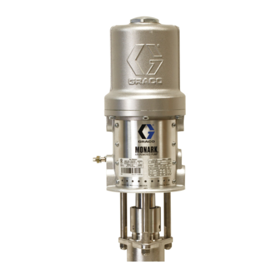
Monark Air Motors
180 psi (12 bar, 1.2 MPa) Maximum Air Working Pressure
Model 204–237, Series M
For in-line mounting
Model 206–955, Series G
For stanchion tube mounting
Model 205–997, Series G
Model 215–363, Series A
Model 945–972, Series A
Model 222–791, Series A
For 3 tie rod mounting
Model 207–546, Series F (Sanitary Pump)
For hinged clamp mounting
GRACO INC. P.O. BOX 1441 MINNEAPOLIS, MN 55440–1441
COPYRIGHT 1970, GRACO INC.
Graco Inc. is registered to I.S. EN ISO 9001
307–043
Rev. N
Supersedes M
05702
Advertisement
Table of Contents

Related Manuals for Graco Monark G Series 205-997


Summarization of Contents
Warnings and Symbols
Warning Symbol
Defines the symbol used to alert users to potential serious injury or death.
Caution Symbol
Defines the symbol used to alert users to potential equipment damage or destruction.
Safety Hazards
Injection Hazard Details
Details the severe risks of fluid injection and the need for immediate medical attention.
Moving Parts Hazard Details
Warns about the danger of pinching or amputation from moving parts.
Fire and Toxic Hazards
Fire and Explosion Hazard
Outlines precautions against fire and explosion due to improper grounding or ventilation.
Toxic Fluid Hazard
Addresses the risks of hazardous fluids and fumes, emphasizing protective measures.
Installation
Grounding Procedures
Explains essential grounding steps for safe operation and to prevent static sparking.
Air Motor Service
Pressure Relief Procedure
Details critical steps to safely relieve system pressure before servicing.
Disassembly Steps
Provides step-by-step instructions for taking apart the air motor assembly.
Air Motor Reassembly
Reassembly Steps 1-6
Covers initial reassembly steps, focusing on valve and piston assembly.
Reassembly Steps 7-11
Continues reassembly with valve nut and lockwire installation.
Parts Identification
Hinged Clamp Mounting Parts
Lists and illustrates parts for the Sanitary Model 207-546, Series F.
Stanchion Tube Mounting Parts
Lists and illustrates parts for Model 206-955, Series G.
3 Tie Rod Mounting Parts
Lists and illustrates parts for Models 205-997, 215-363, 945-972, 222-791.
Need help?
Do you have a question about the Monark G Series 205-997 and is the answer not in the manual?
Questions and answers