Table of Contents
Advertisement
M
M
M
M
X
5
M
X
5
M
X
5
M
X
5
0
M
X
5
0
M
X
5
0
B
e
n
B
e
n
B
e
n
u
l
t
i
m
u
l
t
i
m
u
l
t
i
m
0
0
6
-
6
0
0
6
-
0
0
6
-
6
0
-
6
0
6
0
-
6
6
0
-
6
U
s
e
r
'
s
M
a
n
u
U
s
e
r
'
s
M
a
n
u
U
s
e
r
'
s
M
a
n
Pôle Test et Mesure CHAUVIN ARNOUX
Tel. +33 (0)4.50.64.22.22 -Fax +33 (0)4.50.64.22.00
c
h
t
o
c
h
t
o
c
h
t
o
e
t
e
e
t
e
e
t
e
0
0
0
p
6
0
0
0
p
6
0
0
0
p
0
0
0
p
0
0
0
0
p
0
0
0
0
p
a
l
a
l
u
a
l
Parc des Glaisins
6, avenue du Pré de Challes
F -74940 ANNECY-LE-VIEUX
X03965A01 - Ed. 01 - 04/13
p
p
p
r
s
r
s
r
s
t
s
t
s
t
s
t
s
t
s
t
s
Advertisement
Table of Contents

Related Manuals for Metrix MX 5006


Summary of Contents for Metrix MX 5006
- Page 1 Pôle Test et Mesure CHAUVIN ARNOUX Parc des Glaisins 6, avenue du Pré de Challes F -74940 ANNECY-LE-VIEUX Tel. +33 (0)4.50.64.22.22 -Fax +33 (0)4.50.64.22.00 X03965A01 - Ed. 01 - 04/13...
-
Page 2: Table Of Contents
Maintenance.................................. 6 Replacing the fuse................................. 6 Prop....................................6 Communication interface............................... 6 Description of the instruments ........................7 MX 5006, MX 5060 front panel............................7 MX 5006, MX 5060 back ............................... 7 Functional description............................. 8 Display unit..................................8 Switch...................................10 Keypad ..................................11 Preparation for use...............................16... -
Page 3: General Directions
We thank you for this sign of confidence in the quality of our products. The line of instruments to which it belongs comprises the following models: MX 5006 6000pts TRMS MX 5060 60000pts TRMS Range 60mV It complies with safety standard NF EN 61010-1 + NF EN 61010-2-030 concerning electronic measuring instruments. -
Page 4: Symbols On The Instrument
The spent batteries must not be treated as ordinary waste. Take them in to the appropriate collection point for recycling. The CE marking indicates conformity with the European "Low Voltage", "EMC", "WEEE" and "RoHS" directives. USB (MX 5060, only) Benchtop multimeters, 6000 and 60000 points... -
Page 5: Warranty
General directions General instructions (continued) This equipment is warranted for 3 years against any defect of materials or Warranty workmanship, in accordance with the general terms of sale. During the warranty period, the instrument may be repaired only by the manufacturer, who reserves the right to repair the instrument or to replace it or part of it. -
Page 6: Service
Adjust the prop to the desired position • Release the 2 pushbuttons to lock the handle in position Communication The MX 5060 has a USB communication interface, used: interface • to configure and read the data measured by the instrument (using SX- DMM software), •... -
Page 7: Description Of The Instruments
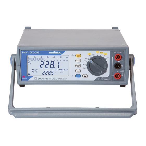
Description of the instruments Description of the instruments Front panel MX 5006 LCD (6000pts) Keypad Switch Terminal block MX 5060 LCD (60000pts) Keypad Switch Terminal block Rear panel MX 5006 Reminders Switch Power connector, ON/OFF 110V or 230V MX 5060... -
Page 8: Functional Description
Functional description Functional description Display unit MX 5006 double display 6000pts MX 5060 double display 60000pts Quantities • AC voltage measurement at low impedance (VLowZ) LowZ measured • AC voltage measurement • DC or AC+DC voltage measurement at high impedance (V) AC/DC •... - Page 9 Functional description Functional description (continued) Symbols Designation Measurement of the RMS AC signal Measurement of the DC signal Measurement of the TRMS AC and DC signal AC + DC Automatic range switching AUTO ΔREL Values relative to a reference ΔMem Presence of a reference value in memory Storage and display of stored values HOLD...
-
Page 10: Switch
Functional description Functional description (continued) Switch The switch setting determines the measurement function chosen. The rotation of the switch has priority over key presses. The change from one position to another resets the configuration of the measurement mode. The change from one measurement function to another deactivates the key, if the HOLD mode was selected. -
Page 11: Keypad
Functional description Functional description (continued) The keypad has the following function keys: Keypad MODE AC/DC RANGE MAX/MIN/PEAK ΔREL HOLD MLI bandwidth filter ( The keys are taken into account and applied when pressed. If the key press is validated, the instrument beeps. General rules For the keys, 2 types of possible action are distinguished: •... - Page 12 Functional description Functional description (continued) Summary table Successive short presses Long press of the keys AC/DC MODE -Choice of AC, DC, or AC+DC coupling Choice of bargraph style: -Access to the second function (yellow marking Bargraph graduated from on the front panel) zero to full scale or with central zero -In the ∆REL or MAX/MIN PEAK plus ∆REL...
- Page 13 Functional description Functional description (continued) MAX/MIN PEAK mode Examples of display in Measured signal: 230V, 50Hz: the V function AC+DC Present value of the signal Frequency of the signal for the MAX value: First press on the key : Present value of the signal MAX value The measured signal changes to 250V, 50Hz: Present value of the signal...
- Page 14 Functional description Functional description (continued) Mode ΔREL Examples of display Measured signal: 1V, 100Hz: in the V AC+DC function Present value of the signal Frequency of the signal Activation of the Δ REL mode by a short press on the key : ΔREL = (present value - reference value) Reference value...
- Page 15 Functional description Functional description (continued) Functions of the switch and keys To access the , and functions, set the switch to the function chosen. Here are the possible combinations according to the type of measurement: Range ΔREL Type of measurement Max/Min Peak ±...
-
Page 16: Preparation For Use
(A, B, C, etc.), • the software version • the instrument model (MX 5006 or MX 5060). A third short press is used to exit from the mode. Switching to standby Set the switch to “OFF”. Benchtop multimeters, 6000 and 60000 points... -
Page 17: How Are The Various Quantities Measured
How are the various quantities measured? How are the various quantities measured? 1. Voltage measurement AC voltage measurement, or measurement of an AC voltage superposed on a DC voltage, or DC voltage measurement at high impedance. AC voltage measurement at high impedance This position is provided to allow measurements in electrical installations. -
Page 18: Current Measurement
How are the various quantities measured? How are the various quantities measured? (continued) 2. Current 1. Set the switch to measurement 2. Select the type of signal, AC+DC, AC, or DC, by pressing Depending on what you select, the screen displays AC, DC, or AC+DC. 3. -
Page 19: Frequency Measurement
How are the various quantities measured? How are the various quantities measured? (continued) 3. Frequency 1. Set the switch to measurement 2. Connect the black lead to the “COM” terminal and the red lead to “+”. 3. Place the test probes on the terminals of the circuit to be measured. Connect the instrument as for a voltage measurement 4. -
Page 20: Diode Test
How are the various quantities measured? How are the various quantities measured? (continued) 6. Diode test 1. Set the switch to 2. Press twice; the “ ” symbol is displayed. 3. Connect the black lead to the “COM” terminal and the red lead to “+”. 4. -
Page 21: Temperature Measurement
How are the various quantities measured? How are the various quantities measured? (continued) 8. Temperature 1. Set the switch to measurement 2. Press to switch the temperature unit (°C or °F) between the two display units. The unit displayed as default on the main display unit is °C. 3. -
Page 22: Measurement On An Mli Type Speed Variator
How are the various quantities measured? How are the various quantities measured? (continued) 9. Measurement on an 1. Set the switch to MLI type speed variator 2. Select the filter by pressing Voltage measurement 3. Connect the black lead to the “COM” terminal and the red lead to “+”. 4. -
Page 23: Technical Characteristics Of Mx 5006
Technical characteristics of the MX 5006 Technical characteristics of the MX 5006 Accuracy: Only values with tolerances or limits are guaranteed values. "n% + nD" means Values without tolerances are given for guidance (standard NFC42670). "n% of the reading The technical specifications are guaranteed only after 30 minutes of warming up. Except + n Digit"... - Page 24 Technical characteristics of the MX 5006 Technical characteristics of the MX 5006 (continued) @ 1kHz Specified Additional Operating Uncertainty Input Peak Range measurement Resolution uncertainty Bandwidth range (±) impedance factor range F (Hz) // < 50 pF 1% L + 45<F<65Hz 0 to 60.0 to...
- Page 25 Technical characteristics of the MX 5006 Technical characteristics of the MX 5006 (continued) CURRENTS Particular reference conditions: DC current µA range: Measuring a strong current for a long time can cause a temperature rise in some components. In this case, it is necessary to wait some time for the metrological characteristics specified in µA to be restored.
- Page 26 Technical characteristics of the MX 5006 Technical characteristics of the MX 5006 (continued) AC and DC current Warning: the sum AC+DC must never exceed the range, 600mA, or 60mA, or 6000µA, or 6A, or 10A, as the case may be. The AC component must represent at least 5% of the amplitude of the AC+DC total for it to be possible to measure it.
- Page 27 Technical characteristics of the MX 5006 Technical characteristics of the MX 5006 (continued) Resistance Protection: 1414Vpk Particular reference conditions: The (+COM) input must not have been overloaded following the accidental application of a voltage to the input terminals with the switch set to Ω or T°. If this happens, the return to normal may take about ten minutes.
- Page 28 Technical characteristics of the MX 5006 Technical characteristics of the MX 5006 (continued) Temperature Protection: 1414Vpk Particular reference conditions: An internal temperature rise may have been caused by: measurement of a strong current for a long time, overload of the +COM input with the switch set to T° or Ω. In this case, it is necessary to wait some time to recover the specified metrological characteristics.
- Page 29 Technical characteristics of the MX 5006 Technical characteristics of the MX 5006 (continued) Influence Variation in the Quantity of Range of Quantity influence influence influenced nominal range of use typical 0.01% L ±0.2 D / 1°C 0.02% L ±0.25 D /1°C mV, V 0.08% L ±0.2 D / 1°C 0.15% L ±0.25 D /1°C...
-
Page 30: Technical Characteristics Of Mx 5060
Technical characteristics of the MX 5060 Technical characteristics of the MX 5060 Accuracy: Only values with tolerances or limits are guaranteed values. "n% + nD" means Values without tolerances are given for guidance (standard NFC42670). "n% of the reading The technical specifications are guaranteed only after 30 minutes of warming up. - Page 31 Technical characteristics of the MX 5060 Technical characteristics of the MX 5060 (continued) 60mV range: Measuring a strong current or measuring a current for a long time may cause a temperature rise of some components. @ 1kHz Additional Specified Uncertainty...
- Page 32 Technical characteristics of the MX 5060 Technical characteristics of the MX 5060 (continued) CURRENTS Particular reference conditions: DC current µA range: Measuring a strong current for a long time may cause a temperature rise of some components. In this case, it is necessary to wait some time for the metrological characteristics specified in µA to be...
- Page 33 Technical characteristics of the MX 5060 Technical characteristics of the MX 5060 (continued) AC and DC current AC+DC TRMS Warning: the sum AC+DC must never exceed the range, 600mA, or 60mA, or 6000µA, or 6A, or 10A, as the case may be.
- Page 34 Technical characteristics of the MX 5060 Technical characteristics of the MX 5060 (continued) Frequency Protection: 1414Vpk Particular reference conditions: 150mV<U<600V Switch set to "Hz", measurement of the When the switch is set to Hz, the 300Hz filter is not in service.
- Page 35 Technical characteristics of the MX 5060 Technical characteristics of the MX 5060 (continued) Audible Protection: 1414Vpk continuity Response time <100ms Open-circuit Range Resolution Uncertainty Measurement current voltage Audible signal triggered 600Ω 0.01Ω < 5V < 1.1mA < 30Ω ±5Ω Diode Test...
- Page 36 Technical characteristics of the MX 5060 Technical characteristics of the MX 5060 (continued) Temperature Specified Range Operating range Resolution Uncertainty (±) measurement range (continued) -200.0°C to 200.0°C -60.0°C to 200.0°C 0.1°C 0.5% L ±2°C -328.0°F to 392.0°F -76.0°F to 392.0°F 0.1°F...
- Page 37 Technical characteristics of the MX 5060 Technical characteristics of the MX 5060 (continued) Influence Variation in the Quantity of Range of Quantity influence influence influenced nominal range of typical 0.01% L ±0.2 D / 1°C 0.02% L ±0.25 D / 1°C 0.08% L ±0.2 D / 1°C...
-
Page 38: General Characteristics
General characteristics General characteristics Environmental Altitude <2000m conditions Reference range 23°C ±5°C Specified range of use 0°C to 40°C Influence of temperature see §. Influences Relative humidity 0% to 80% from 0°C to 35°C 0% to 70% from 35°C to 40°C limited to 70% for the 5 and 50 Ω... -
Page 39: Supply
• Lead, 1.5m, straight/straight, black • Test probe, CAT IV, 1kV, red • Test probe, CAT IV, 1kV, black • USB cord MX 5060 • K thermocouple, wire + adapter optional • SX-DMM BT software • Fuse, 1000V, 11A, 10x38mm (consult our regional Manumesure technical...
Need help?
Do you have a question about the MX 5006 and is the answer not in the manual?
Questions and answers