Table of Contents
Advertisement
Quick Links
Download this manual
See also:
User Manual
Office: Jl. Radin Inten II No. 62 Duren Sawit, Jakarta 13440 - Indonesia
Workshop: Jl. Pahlawan Revolusi No. 22B, Jakarta 13430 - Indonesia
Phone: 021-8690 6777 (Hunting)
MX 58HD
Notice de fonctionnement
User's manual
Bedienungsanleitung
Libretto d'istruzioni
Manual de instrucciones
ENGLISH -
page 16
Chapter
Mobile: +62 816 1740 8925
Fax: 021-8690 6771
Fax: 021-8690 6777
II
Advertisement
Table of Contents

Related Manuals for Metrix MX 58HD


Summary of Contents for Metrix MX 58HD
- Page 1 MX 58HD Notice de fonctionnement User's manual Bedienungsanleitung Libretto d’istruzioni Manual de instrucciones ENGLISH - page 16 Chapter Mobile: +62 816 1740 8925 Office: Jl. Radin Inten II No. 62 Duren Sawit, Jakarta 13440 - Indonesia Workshop: Jl. Pahlawan Revolusi No. 22B, Jakarta 13430 - Indonesia...
- Page 2 Multimètre digital portable...
- Page 3 LEGENDE / CAPTION / BESCHREIBUNG / LEGENDA / LEYENDA Borne d'entrée calibres 11, 12, 13, 14, 15 11 Mesure de tensions alternatives Entrée de référence du multimètre 12 Mesure de tensions 500 mV Borne d'entrée calibres mA 13 Mesure de tensions continues Borne d'entrée calibre 10 A 14 Mesure de résistance Mise sous tension (sélection fonctions secondaires)
- Page 4 Chapter II CONTENTS 1. GENERAL INSTRUCTIONS......................... 17 1.1. Precautions and safety measures ....................17 1.2. Protection devices .......................... 18 1.3. Safety devices ..........................19 1.4. Warranty ............................19 1.5. Maintenance ........................... 21 1.6. Unpacking - Repacking ........................19 2. DESCRIPTION............................20 2.1.
-
Page 5: General Instructions
Chapter II GENERAL INSTRUCTIONS You have just acquired a 5000 count-portable digital multimeter and we thank you for your confidence. This instrument complies with the specification of EN publication 61010-1, concerning safety requirements for electronic measuring apparatus. To get the best service from this instrument, read carefully this user’s manual and respect the detailed safety precautions. -
Page 6: Protection Devices
Chapter II ∗ When performing current measurements, never change of range, do not connect or disconnect leads without first isolating the current. If you do, there is a risk of generating surge currents which can blow the fuses or damage the instrument. ∗... -
Page 7: Safety Devices
Chapter II 1.3. Safety devices ∗ The battery unit and fuses cannot be accessed without first disconnecting the measuring leads. ∗ When measuring voltages above 24 V, the symbol blinks on the display. ∗ If the maximum range is repeatedly exceeded, an intermittent audible signal indicates the risk of electric shock. -
Page 8: Description
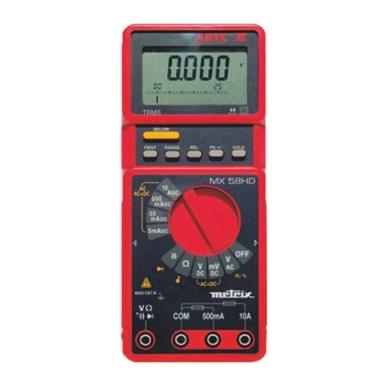
Chapter II DESCRIPTION This multimeter is one of the ASYC II (Advanced SafetY Concept, third generation) range, designed for a high degree of user safety, maximum protection and unrivalled performance. 2.1. Selector switch It is a standalone, handheld professional measuring instrument, capable of measuring the following quantities (accessed by the eleven-position rotary selector switch) : •... -
Page 9: Commissioning
Chapter II COMMISSIONING 3.1. Connecting the test leads Connect the black lead to the COM socket (for all measurements). Depending on the position of the selector switch, connect the red lead as follows: Rotary selector switch position Input terminal VΩ , Ω, , mV 10 A... -
Page 10: Multimeter Maintenance
Chapter II 3.5. Multimeter maintenance 3.5.1. Fuse self-test When fuse F1 (0.63 A) or F2 (11 A) is blown, the display shows “FUSE.1” or “FUSE.2”, accordingly. If both fuses are blown, the display shows “FUSES”. Replace the fuse or fuses concerned. Note Fuse F1 cannot be tested unless the switch is set to a mA position. -
Page 11: Functional Description
Chapter II FUNCTIONAL DESCRIPTION 4.1. SEL/ON key This can be used to switch on the multimeter again after an automatic shutdown. It can also be used to access secondary functions associated with the selector switch positions. The flowcharts below define these various functions. 4.1.1. - Page 12 Chapter II 4.1.3. V position DC voltage measurement SEL/ON AC+ DC voltage measurement SEL/ON 4.1.4. Ω position Resistance measurement SEL/ON Continuity test SEL/ON 4.1.5. position Capacitance measurement SEL/ON Diode voltage measurement SEL/ON Portable digital multimeter...
-
Page 13: Range Key
Chapter II 4.1.6. 5 mA / 50 mA / 500 mA / 10 A positions DC current measurement SEL/ON AC current measurement SEL/ON AC+DC current measurement SEL/ON 4.2. RANGE key • In AUTO mode to switch to MANUAL mode (short press). •... -
Page 14: Hold Key
Chapter II 4.5. HOLD key Short press : Sets the display on the current value. Long press : Accesses or quits the “autostore” mode. Can be accessed in the V , mV, V positions. Autostore Set the probes on the point to be measured. An audio signal indicates if the measurement is stable. -
Page 15: Technical Specifications
Chapter II TECHNICAL SPECIFICATIONS Only those values assigned tolerances or limits are guaranteed values. Values without tolerances are given for information only (French standard NFC 42670). The technical specifications are guaranteed only after 30 min warm-up period. Except special indication, they are valid from 5 to 100 % of the range of measurement. {Accuracy : ‘’n%R + nD’’... -
Page 16: Dc Current
Chapter II 5.3. DC current Selector Max. voltage Fuses ∗ Accuracy Protection Resolution switch drop 5 mA 1 µA 700 mV 50 mA 0.2 % R + 2 D F1 + F2 10 µA 600 V 500 mA 1.5 V 100 µA 10 A∗∗... -
Page 17: Capacitance
Chapter II 5.6. Capacitance Note Discharge all capacitors before taking measurements. Measurement Max measurement Ranges Accuracy Resolution Protection∗ current time 100 nA 10 pF 50 nF∗∗ 500 nF 1 µA 100 pF 0.5 s 1% R + 2D 5 µF 10 µA 1 nF 600 V... -
Page 18: General Specifications
Chapter II GENERAL SPECIFICATIONS Adjustment This multimeter incorporates a non-volatile memory containing the adjustment characteristics for all measurement ranges. This enables the instrument to be re-adjusted via a serial link without opening the instrument. It is supplied with a certificate of verification. Safety according to EN 61010-1 Environment... - Page 19 6.1.1. Supplied with the multimeter One set of test leads with safety probes One 6F22 9 V battery One spare 11 A fuse, 10 x 38 mm, rupture capacity 30 kA / 1000 V One spare 0.63 A fuse, 5 x 20 mm, rupture capacity 1.5 kA / 500 V One operating manual One rubber shock-absorber sheath 6.1.2.
Need help?
Do you have a question about the MX 58HD and is the answer not in the manual?
Questions and answers