Table of Contents
Advertisement
Available languages
Available languages
Multimètre - Multimeter
Multimeter - Multimetro - Multímetro
50 000 points - counts - Punkte - punti - puntos
Copyright ©
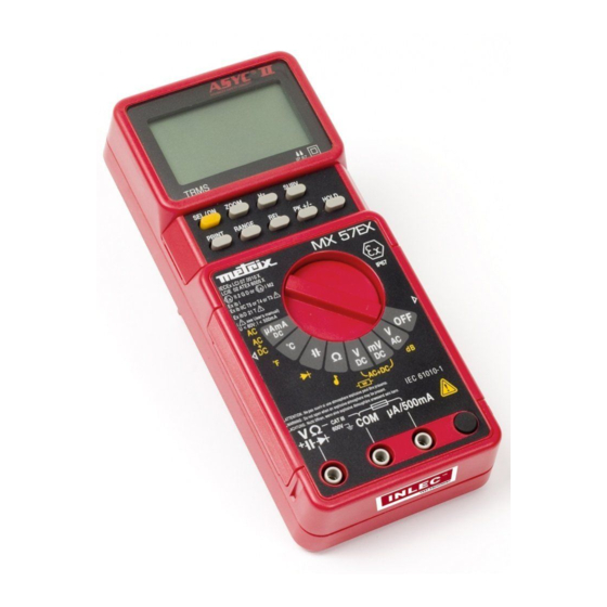
MX 57 EX
de sécurité intrinsèque
intrinsically safe
mit Eigensicherheit
a sicurezza intrinseca
de seguridad intrínseca
Notice de fonctionnement
User's manual
Bedienungsanleitung
Manual de instrucciones
FRANÇAIS - page 4 -
ENGLISH -
DEUTSCH - Seite 44 -
ITALIANO -
ESPAÑOL - página 84 - Capítulo
Chapitre
page 24 -
Chapter
Kapitel
pagina 64 - Capitolo
X02137D00 - Ed. 3 - 04/16
I
II
III
IV
V
Advertisement
Chapters
Table of Contents

Related Manuals for Metrix MX 57 EX


Summary of Contents for Metrix MX 57 EX
- Page 1 MX 57 EX Multimètre - Multimeter Multimeter - Multimetro - Multímetro 50 000 points - counts - Punkte - punti - puntos de sécurité intrinsèque intrinsically safe mit Eigensicherheit a sicurezza intrinseca de seguridad intrínseca Notice de fonctionnement User's manual...
- Page 2 X02137D00 - Ed. 3 - 04/16 Chapitre I IECEx LCI 07.0010 X LCIE 02 ATEX 6005 X II 2 G D or I M2 Ex ib I Ex ib IIC T5 or T4 or T3 Ex ib D 21 IP6X T IP 67 U <...
- Page 3 Chapitre I X02137D00 - Ed. 3 - 04/16 LEGENDE / LEGEND / BESCHREIBUNG / LEGENDA / LEYENDA Borne d'entrée calibres (10,11,12,13,14,16) 11 Mesure de tension 500 mV Entrée de référence du multimètre 12 Mesure de tension continue Borne d'entrée calibre µA mA (15) 13 Mesure de résistance Mise sous tension (fonctions secondaires) 14 Mesure de capacité...
-
Page 4: Table Of Contents
X02137D00 - Ed. 3 - 04/16 Chapitre I TABLE DES MATIERES 1. INSTRUCTIONS GENERALES ..................... 5 1.1. Consignes de sécurité ......................5 1.2. Dispositifs de protection ......................7 1.3. Dispositifs de sécurité ......................7 1.4. Garantie ........................... 7 1.5. Maintenance ..........................8 1.6. -
Page 5: Instructions Generales
Le multimètre MX 57 EX est conforme à la norme de sécurité EN 61010-1 (2010) + EN 61010-2- 030 (2010) double isolation, relative aux instruments de mesures électroniques. Il a été conçu pour une utilisation, en intérieur, dans un environnement de degré... - Page 6 X02137D00 - Ed. 3 - 04/16 Chapitre I Les paramètres électriques du circuit de sécurité intrinsèque doivent respecter les valeurs suivantes : U 60 V (valeur crête) ou I 500 mA Avant chaque utilisation, 1.1.3. Pendant l'utilisation Ne jamais dépasser les valeurs limites de protection indiquées dans les spécifications propres à...
-
Page 7: Dispositifs De Protection
Chapitre I X02137D00 - Ed. 3 - 04/16 Lorsque l'appareil est ouvert, certains condensateurs internes peuvent conserver un potentiel dangereux, même après avoir mis l'appareil hors tension. En cas de défauts ou contraintes anormales, mettre l'appareil hors service et empêcher son utilisation jusqu'à ce qu'il soit procédé à sa vérification. Il est recommandé... -
Page 8: Maintenance
X02137D00 - Ed. 3 - 04/16 Chapitre I 1.5. Maintenance La maintenance de cet appareil ne peut être effectuée que par une personne ayant suivi une formation sur les règles de sécurité intrinsèque. Renseignements et coordonnées sur demande : Tél. 02.31.64.51.55 - Fax 02.31.64.51.09 1.6. -
Page 9: Description De L'appareil
Chapitre I X02137D00 - Ed. 3 - 04/16 DESCRIPTION DE L'APPAREIL Ce multimètre fait partie de la famille ASYC II (Advanced SafetY Concept 2ème génération) conçue pour donner à l'utilisateur une haute garantie de sécurité, une protection maximale et un niveau de performance inégalés. -
Page 10: Mise En Service
X02137D00 - Ed. 3 - 04/16 Chapitre I MISE EN SERVICE 3.1. Connexion des cordons Connecter le cordon noir dans la douille COM (ceci pour toutes les mesures à effectuer). Selon la position du commutateur rotatif, connecter le cordon rouge de la façon suivante : Position du commutateur rotatif Borne d'entrée , mV... -
Page 11: Entretien Du Multimètre
Chapitre I X02137D00 - Ed. 3 - 04/16 3.5. Entretien du multimètre Attention ! Toute intervention interne ne peut être effectuée que hors zone dangereuse. 3.5.1. Auto-vérification des fusibles Fusible F1 : Lorsque le commutateur est placé sur la position µA mA et que le fusible F1 de sécurité... -
Page 12: Description Fonctionnelle
X02137D00 - Ed. 3 - 04/16 Chapitre I DESCRIPTION FONCTIONNELLE 4.1. Touche SEL/ON Elle peut être utilisée pour remettre sous tension le multimètre après un arrêt automatique. Elle permet aussi d'accéder aux fonctions secondaires liées à chaque position du commutateur. Les tableaux suivants définissent ces différentes fonctions. 4.1.1. - Page 13 Chapitre I X02137D00 - Ed. 3 - 04/16 4.1.3. Position mV Mesure tension DC gamme 500 mV SEL/ON Mesure tension AC + DC gamme 500 mV SEL/ON 4.1.4. Position Mesure de résistances SEL/ON Test continuité SEL/ON 4.1.5. Position Mesure de capacités SEL/ON Mesure de tension diode SEL/ON...
- Page 14 X02137D00 - Ed. 3 - 04/16 Chapitre I 4.1.6. Position µA mA Mesure courant continu SEL/ON Mesure courant AC SEL/ON Mesure courant AC + DC SEL/ON 4.1.7. Position C Mesure de température Court-circuit des SEL/ON > 1 sec. SEL/ON < 1 sec. connexions Sélection de la sonde Changement d'unité...
-
Page 15: Touche Range
Chapitre I X02137D00 - Ed. 3 - 04/16 4.2. Touche RANGE Elle permet : En mode AUTO, de passer en MANUEL (appui court) En mode MANUEL, de passer à la gamme suivante (appui court) ou de revenir en mode AUTO (appui long) Mesures concernées : tension (sauf gamme 500 mV), capacité, résistance, courant Si le changement de gammes lors de la mesure précédente (Tension / Courant) était en mode manuel, il pourrait être nécessaire d'adapter cette gamme de mesure au... -
Page 16: Touche Surv
X02137D00 - Ed. 3 - 04/16 Chapitre I 4.7. Touche SURV Un appui long sur cette touche permet d'entrer dans le mode de surveillance (ou d'en sortir), c'est-à-dire d'enregistrer les valeurs : minimale (MIN), maximale (MAX) ou moyenne glissante (AVG) de la mesure en cours (durée de variation 500 ms). -
Page 17: Specifications Techniques
Chapitre I X02137D00 - Ed. 3 - 04/16 SPECIFICATIONS TECHNIQUES Seules les valeurs affectées de tolérances ou les limites constituent des valeurs garanties. Les valeurs sans tolérances sont données à titre indicatif (norme NFC 42670). CEI 485}. ( ) Lorsque les bornes de mesure seront raccordées à un circuit de sécurité intrinsèque, les paramètres électriques du circuit de sécurité... -
Page 18: Courants Continus
X02137D00 - Ed. 3 - 04/16 Chapitre I Nombre de points : 50 000 (ou 5000 voir §. 3.4.) Sélection des gammes : auto. ou manuelle pour les gammes 5 V, 50 V, 500 V, 600 V Réjection de mode commun : à... -
Page 19: Résistances / Mode Continuité
Chapitre I X02137D00 - Ed. 3 - 04/16 Nombre de points : 50 000 (ou 5000 voir §. 3.4.) Sélection des gammes : auto. ou manuelle pour les gammes 500 µA, 5 mA, 50 mA, 500 mA Erreur additionnelle en fonction du facteur crête : 0,2 % pour un facteur crête de 2 à 3 0,5 % pour un facteur crête de 3 à... -
Page 20: Mesure De Tension De Seuil Diodes
X02137D00 - Ed. 3 - 04/16 Chapitre I 5.7. Mesure de tension de seuil diodes Tensions mesurables : 0 à 2 V Courant de mesure : 1 mA 20 % Résolution : 1 mV Protection : 600 V ré-armable automatiquement 5.8. -
Page 21: Rapport Cyclique
Chapitre I X02137D00 - Ed. 3 - 04/16 5.11. Rapport cyclique : % + , % - % - = T x 100 % + = T x 100 Résolution : 0,01 % Durée minimale pour ou T - 2 µs Durée maximale pour T : 0,8 s Durée minimale pour T :... -
Page 22: Caracteristiques Generales
X02137D00 - Ed. 3 - 04/16 Chapitre I CARACTERISTIQUES GENERALES Ajustage Le multimètre MX 57 EX est équipé d'une mémoire non volatile contenant les caractéristiques d'étalonnage de toutes les gammes de mesure. L'appareil est livré accompagné d'un certificat de conformité. Sécurité... -
Page 23: Accessoires
Chapitre I X02137D00 - Ed. 3 - 04/16 Cet appareil a été conçu conforme aux normes CEM en vigueur et sa compatibilité a été testée conformément à la norme suivante : Emission (cl. A) et Immunité NF EN 61326-1 (2013) Etanchéité... - Page 24 X02137D00 - Ed. 3 - 04/16 Chapter II USER'S MANUAL CONTENTS GENERAL INSTRUCTIONS ....................25 1.1. Precautions and safety measures ..................25 1.2. Protection devices ......................27 1.3. Safety devices ........................27 1.4. Warranty ..........................27 1.5. Maintenance ........................28 1.6.
-
Page 25: General Instructions
This MX 57 EX multimeter complies with safety standard EN 61010-1 (2010) + EN 61010-2 (2010) double insulation, relative to electronic measuring instruments. This instrument has been designed for indoor use, in an environment with pollution level 2, at an altitude of less than 2000m, at a temperature from 0 to 50 C, with relative humidity <... - Page 26 X02137D00 - Ed. 3 - 04/16 Chapter II 1.1.3. During use Never exceed the protective limiting values given in the characteristics specific to each type of measurement. When the multimeter is linked to measurement circuits, do not touch unused terminals. When the scale of the value to be measured is unknown, check that the scale initially set on the multimeter is the highest possible or, wherever possible, choose the autoranging mode.
-
Page 27: Protection Devices
Chapter II X02137D00 - Ed. 3 - 04/16 1.2. Protection devices ASYC II series instruments are fitted with various protection devices : A protection by varistors allows a chopping of transient overvoltages present at the terminals of measurement. A PTC (Positive Temperature Coefficient) resistor protects against permanent overvoltages of up to 600 V during resistance, capacitance and diode test measurements. -
Page 28: Maintenance
X02137D00 - Ed. 3 - 04/16 Chapter II 1.5. Maintenance Maintenance of this unit can only be performed by a person who has undergone training on intrinsic safety rules. Return your instrument to your distributor for any work to be done within or outside the guarantee. -
Page 29: Description
Chapter II X02137D00 - Ed. 3 - 04/16 DESCRIPTION This multimeter is one of the ASYC II (Advanced SafetY Concept, second generation) range, designed for a high degree of user safety, maximum protection and unrivalled performance. 2.1. Selector switch This standalone, handheld professional measuring instrument is capable of measuring the following quantities (accessed by the eight-position rotary selector switch) : AC voltages with AC (or RMS) capacitive coupling AC voltages with AC+DC (or TRMS) direct coupling... -
Page 30: Commissioning
X02137D00 - Ed. 3 - 04/16 Chapter II COMMISSIONING 3.1. Connecting the test leads Connect the black lead to the COM socket (for all measurements). Depending on the position of the selector switch, connect the red lead as follows : Rotary selector switch position Input terminal , mV... -
Page 31: Multimeter Maintenance
Chapter II X02137D00 - Ed. 3 - 04/16 3.5. Multimeter maintenance Any internal intervention can only be performed outside the danger zone. 3.5.1. Fuse self-test F1 Fuse: When the switch is set to the µA mA position and the (0.500 A, 125 V) F1 fuse of intrinsic safety is cut, the display shows "FUSE". -
Page 32: Functional Description
X02137D00 - Ed. 3 - 04/16 Chapter II FUNCTIONAL DESCRIPTION 4.1. SEL/ON key This can be used to switch on the multimeter again after an automatic shutdown. It can also be used to access secondary functions associated with the selector switch positions. The flowcharts below define these various functions. - Page 33 Chapter II X02137D00 - Ed. 3 - 04/16 4.1.3. mV position DC voltage measurement 500 mV range SEL/ON AC + DC voltage measurement 500 mV range SEL/ON 4.1.4. position Resistance measurement SEL/ON Continuity test SEL/ON 4.1.5. position Capacitance measurement SEL/ON Diode voltage measurement SEL/ON Warning !
- Page 34 X02137D00 - Ed. 3 - 04/16 Chapter II 4.1.6. µA mA position DC current measurement SEL/ON AC current measurement SEL/ON AC+DC current measurement SEL/ON LECTRICAL PECIFICATIONS OF THE NTRINSICALLY IRCUITS 500 mA 4.1.7. C Position Temperature measurement SEL/ON > 1 sec. SEL/ON <...
-
Page 35: Range Key
Chapter II X02137D00 - Ed. 3 - 04/16 4.2. RANGE key In AUTO mode, to switch to MANUAL mode (short press). In MANUAL mode, to select the next range (short press) or return to AUTO mode (long press). Measurements concerned : voltages, capacitance, resistance, currents. When making time measurements (frequency, duty cycle, pulse width, pulse count) : if the range change made during previous measurements (Voltage or Current) was in manual mode, it may be necessary to adapt this measurement range to the signal level... -
Page 36: Surv Key
X02137D00 - Ed. 3 - 04/16 Chapter II 4.7. SURV key If you press this key (long press), you access the surveillance mode (or coming out), in which minimum (MIN), maximum (MAX) and sliding average (AVG) values of the current measurement are stored (capture time 500 ms). -
Page 37: Technical Specifications
Chapter II X02137D00 - Ed. 3 - 04/16 TECHNICAL SPECIFICATIONS Only those values assigned tolerances or limits are guaranteed values. Values without tolerances are given for information only (French standard NFC 42-670). ( ) When the measurement terminals are connected to an intrinsically safe circuit, the electrical specifications of intrinsically safe circuits must conform following values : U 60 V (peak value) or I... -
Page 38: Dc Current
X02137D00 - Ed. 3 - 04/16 Chapter II Number of counts : 50 000 (or 5 000 - refer to §. 3.4.) Range selection : automatic or manual for the 5 V, 50 V, 500 V, 600 V ranges Common mode rejection : at 50 and 60 Hz, better than 80 dB Additional error according to crest factor : 0.2 % for a crest factor of 2 to 3... -
Page 39: Resistance / Continuity
Chapter II X02137D00 - Ed. 3 - 04/16 Number of counts : 50 000 (or 5 000 - refer to §. 3.4.) Range selection : automatic or manual for the 500 µA, 5 mA, 50 mA, 500 mA ranges Additional error according to crest factor : 0.2 % for a crest of 2 to 3 0.5 % for a crest of 3 to 6 (Specification given full scale for a squarewave signal pulse 200 µs wide) Additional error in IAC+DC with a direct current at input : 1 %... -
Page 40: Diode Threshold Voltage Measurement
X02137D00 - Ed. 3 - 04/16 Chapter II 5.7. Diode threshold voltage measurement Measurable voltages : 0 to 2 V Measurement current : 1 mA ± 20 % Resolution : 1 mV Protection : 600 V , can be reset automatically. 5.8. -
Page 41: Duty Cycle
Chapter II X02137D00 - Ed. 3 - 04/16 5.11. Duty cycle: %+, %- % + = T x 100 % - = T x 100 Resolution : 0.01% Minimum duration for or T - : 2 µs Maximum duration for T : 0.8 s Minimum duration for T : 100 µs... -
Page 42: General Specifications
X02137D00 - Ed. 3 - 04/16 Chapter II GENERAL SPECIFICATIONS Adjustment The MX 57 EX multimeter incorporates a non-volatile memory containing the adjustment characteristics for all measurement ranges. It is supplied with a certificate of conformity. Safety acc. to EN 61010-1 (2010) + EN 61010-2-030 (2010) -
Page 43: Accessories Supplied With The Multimeter
Chapter II X02137D00 - Ed. 3 - 04/16 This unit was designed in compliance with the EMC standards in force and its compatibility has been tested in accordance with the following standard : Emission (cl. A) and Immunity NF EN 61326-1 (2013) Sealing IP 67 acc. - Page 44 X02137D00 - Ed. 3 - 04/16 Kapitel III BEDIENUNGSANLEITUNG INHALTSVERZEICHNIS ALLGEMEINE HINWEISE ....................... 45 1.1. Sicherheitsregeln ....................... 45 1.2. Schutzvorrichtungen ......................47 1.3. Sicherheitseinrichtungen ....................47 1.4. Garantie ..........................47 1.5. Wartung, Reparaturen ....................... 48 1.6. Auspacken/Verpacken des Gerätes .................. 48 GERÄTEBESCHREIBUNG ......................
-
Page 45: Allgemeine Hinweise
Dieses Multimeter darf nur von Personen benutzt werden, die die Regeln für Geräte für explosions- gefährdeten Bereichen kennen und entsprechend geschult worden sind. Das Multimeter MX 57 EX kann für Messungen kurzer Dauer an eigensicheren Strom- kreisen der Kategorie ib verwendet werden. Kurze Dauer bedeutet, dass das Multime- ter nicht permanent und nicht als festes Gerät verwendet werden darf. - Page 46 X02137D00 - Ed. 3 - 04/16 Kapitel III Für Ihre Sicherheit verwenden Sie nur die mit dem Gerät gelieferten Kabel. Überprüfen Sie vor jedem Gebrauch, ob diese in einwandfreiem Betriebszustand sind. Verwenden Sie in explosionsgefährdeten Bereichen zusammen mit diesem Multimeter nur Zubehör, das ein Konformitätszertifikat für den Betrieb zusammen mit diesem Multimeter besitzt.
-
Page 47: Schutzvorrichtungen
Kapitel III X02137D00 - Ed. 3 - 04/16 Sollte das Gerät während einer bestimmten Zeit unbenützt bleiben, dann die Batterie entfernen. 1.2. Schutzvorrichtungen Die Geräte der ASYC II - Serie sind mit mehrfachen Schutzvorrichtungen versehen : Eine Varistor-Schutzschaltung filtriert kurzzeitige Überspannungen an der Eigangs- buchse. -
Page 48: Wartung, Reparaturen
X02137D00 - Ed. 3 - 04/16 Kapitel III 1.5. Wartung, Reparaturen Die Wartung dieses Geräts darf nur von einer Person durchgeführt werden, die eine Schu- lung zu den allgemeinen Regeln der Eigensicherheit erhalten hat. Wenden Sie sich an die Niederlassung Ihres Landes. 1.6. -
Page 49: Gerätebeschreibung
Kapitel III X02137D00 - Ed. 3 - 04/16 GERÄTEBESCHREIBUNG Dieses Multimeter gehört zur Familie der ASYC II-Geräte (Advanced SafetY Concept der 2. Ge- neration), die dem Benutzer größtmögliche Sicherheit, optimalen Schutz vor Fehlbedienungen und ein bisher unerreichtes Leistungsspektrum bieten. 2.1. Zentraler Drehschalter Das tragbare, batteriebetriebene Messinstrument für den Elektroprofi ermöglicht folgende durch den 8-stelligen Wahlschalter selektierbare Messungen:... -
Page 50: Inbetriebnahme
X02137D00 - Ed. 3 - 04/16 Kapitel III INBETRIEBNAHME 3.1. Anschluss der Messleitungen Schließen Sie die schwarze Messleitung an die COM-Eingangsbuchse an (dies gilt für alle Messungen !). Je nach Messart und Drehschalterstellung stecken Sie die rote Messleitung in die untengenannte Eingangsbuchse: Drehschalterstellung Eingangsbuchse , mV... -
Page 51: Wartung Des Multimeters
Kapitel III X02137D00 - Ed. 3 - 04/16 3.5. Wartung des Multimeters Achtung ! Eingriffe in das Gerät dürfen nur außerhalb von Gefahrenbereichen durch- geführt werden. 3.5.1. Selbsttest der Sicherungen Sicherung F1 : Befindet sich der Wahlschalter in der Position µA mA und ist die Sicherung F1 für die Eigensicherheit außer Betrieb, zeigt die Anzeige "FUSE". -
Page 52: Funktionsbeschreibung
X02137D00 - Ed. 3 - 04/16 Kapitel III 3.5.4. Pflege Reinigen Sie das Geräts mit einem feuchten Tuch und Seife. Vor der Benutzung trocknen lassen. Keine Lösungsmittel oder abschleifende Mittel benutzen. FUNKTIONSBESCHREIBUNG 4.1. Taste SEL/ON Mit dieser Taste können Sie das Multimeter nach Ansprechen der Abschalteautomatik wiedereinschalten. - Page 53 Kapitel III X02137D00 - Ed. 3 - 04/16 4.1.3. Stellung mV DC Spannungsmessung im Bereich 500 mV SEL/ON AC+DC Spannungsmessung im Bereich 500 mV SEL/ON 4.1.4. Stellung Widerstandsmessung SEL/ON Durchgangsprüfung SEL/ON 4.1.5. Stellung Kapazitätsmessung SEL/ON Messung der Schwellenspannung SEL/ON Achtung ! Führen Sie in Gefahrenbereichen keine Kapazitätsmessungen durch. Tragbares Digital-Multimeter mit Eigensicherheit...
- Page 54 X02137D00 - Ed. 3 - 04/16 Kapitel III 4.1.6. Stellung µA mA DC-Strommessung SEL/ON AC-Strommessung SEL/ON AC+DC-Strommessung SEL/ON LEKTRISCHE ATEN DER IGENSICHEREN TROMKREISE 500 mA 4.1.7. Stellung C Temperatur-Messung SEL/ON > 1 Sek. SEL/ON < 1 Sek. Zuleitungen kurzschließen Wahl des Tastkopfs Einheits-Änderung Pt 100 / Pt 1000 C/ F...
-
Page 55: Taste Range
Kapitel III X02137D00 - Ed. 3 - 04/16 4.2. Taste RANGE Mit dieser Taste können Sie : Von automatischer Bereichswahl auf manuelle Bereichswahl umschalten (Taste kurz drücken). In manueller Bereichswahl durch kurzes Drücken auf den nächsten Bereich umschalten oder durch langes Drücken auf automatische Bereichswahl zurückschalten. Dies betrifft die Messungen von AC- oder DC-Spannungen (außer 500 mV Bereich), Kapazitä- ten oder Widerständen, Strom. -
Page 56: Taste Surv
X02137D00 - Ed. 3 - 04/16 Kapitel III 4.7. Taste SURV Durch langes Drücken dieser Taste stellen Sie den Überwachungsmodus ein (oder aus), d.h. das Gerät speichert laufend die Messwerte ein und ermittelt automatisch den Minimal- wert (MIN), den Maximalwert (MAX) und den gleitenden Mittelwert (AVG) aller bisherigen Messungen (Erfassungszeit 500 ms). -
Page 57: Technische Daten
Kapitel III X02137D00 - Ed. 3 - 04/16 TECHNISCHE DATEN Nur die mit Toleranzen oder mit Grenzwerten angegebenen Daten sind zugesicherte Eigenschaften des Gerätes. Werte ohne Toleranzangaben dienen lediglich zur Information (franz. Norm NFC 42670). ( ) Wenn die Messklemmen mit einem Eigensicherheitskreis verbunden sind, müssen die elektrischen Parameter des Eigensicherheitskreises den folgenden Werten ent- sprechen : U 60 V (Spitzenwert) oder I... -
Page 58: Gleichströme
X02137D00 - Ed. 3 - 04/16 Kapitel III Anzahl Messpunkte : 50 000 (oder 5 000 - siehe Abschnitt 3.4) Bereichsumschaltung : automatisch oder manuell zwischen den Bereichen 5 V, 50 V, 500 V, 600 V Gleichtaktunterdrückung : größer 80 dB bei 50 Hz/60 Hz Zusätzlicher Fehler durch den Scheitelfaktor des Signals : 0,2 % für Scheitelfaktoren zwischen 2 bis 3 0,5 % für Scheitelfaktoren zwischen 3 bis 6... -
Page 59: Widerstände, Durchgangsprüfung
Kapitel III X02137D00 - Ed. 3 - 04/16 Anzahl Messpunkte : 50 000 (oder 5 000 - siehe Abschnitt 3.4.) Bereichsumschaltung : automatisch oder manuell zwischen den Bereichen 500 µA, 5 mA, 50 mA, 500 mA. Zusätzlicher Fehler durch den Scheitelfaktor des Signals : 0,2 % für Scheitelfaktoren zwischen 2 bis 3 0,5 % für Scheitelfaktoren zwischen 3 bis 6 (Fehlerangabe für Rechtecksignal am Bereichsende mit 200 µs Impulsbreite) -
Page 60: Dioden-Schwellenspannung
X02137D00 - Ed. 3 - 04/16 Kapitel III 5.7. Dioden-Schwellenspannung Messbereich : 0 bis 2 V Messstrom : 1 mA 20 % Auflösung : 1 mV Überlastschutz : 600 V mit automatischer Rücksetzung 5.8. dB-Messung Anzeige des Messwertes in "dBm" in Bezug auf einen frei einstellbaren Lastwiderstand zwischen 1 und 9999 (siehe Abschn. -
Page 61: Tastverhältnis
Kapitel III X02137D00 - Ed. 3 - 04/16 5.11. Tastverhältnis : % + , % - % + = T x 100 % - = T x 100 Auflösung : 0,01 % Mindest-Impulsbreite oder T - 2 µs Maximale Impulsbreite für T : 0.8 s Mindest-Impulsbreite für T : 100 µs... -
Page 62: Allgemeine Technische Daten
Kapitel III ALLGEMEINE TECHNISCHE DATEN Kalibrierung Das Multimeter MX 57 EX besitzt einen nicht-flüchtigen Speicher in dem sämtlichen Kalibrierdaten aller Messbereiche abgelegt werden. Dadurch ist eine Nachkalibrierung des Gerätes über seriellen Datenaustausch ohne Öffnen des Gerätes möglich. Bei Auslieferung liegt dem Instrument ein Überprüfungszertifikat bei. -
Page 63: Zubehör (Serienmäßiger Lieferumfang)
Kapitel III X02137D00 - Ed. 3 - 04/16 Dieses Gerät wurde gemäß den geltenden EMV-Normen entwickelt und die Einhaltung dieser Normen wurde gemäß den folgenden Normen geprüft: Aussendung (Kl. A) und Schutz NF EN 61326-1 : 2013 Dichtheit Typ IP 67 gemäß... - Page 64 X02137D00 - Ed. 3 - 04/16 Capitolo IV INDICE ISTRUZIONI GENERALI ......................65 1.1. Norme di sicurezza ......................65 1.2. Dispositivi di protezione ..................... 67 1.3. Dispositivi di sicurezza ...................... 67 1.4. Garanzia ..........................67 1.5. Manutenzione ........................68 1.6. Apertura - Ripristino della confezione ................
-
Page 65: Istruzioni Generali
Il multimetro MX 57 EX può essere utilizzato per delle operazioni di misura di breve durata su dei circuiti di sicurezza intrinseca di categoria ib . Breve durata significa che il multimetro non deve essere utilizzato in permanenza, né... - Page 66 X02137D00 - Ed. 3 - 04/16 Capitolo IV I parametri elettrici del circuito di sicurezza intrinseca devono rispettare i seguenti valori : U 60 V (valore cresta) o I 500 mA In atmosfera esplodibile, utilizzare solo degli accessori che possiedono un certificato di 1.1.3.
-
Page 67: Dispositivi Di Protezione
Capitolo IV X02137D00 - Ed. 3 - 04/16 1.2. Dispositivi di protezione Gli apparecchi della serie ASYC II sono dotati di vari dispositivi che ne assicurano la protezione : una protezione tramite resistenze consente lo spianamento delle sovratensioni transitorie. una resistenza CTP (Coefficiente di Temperatura Positivo) protegge dalle sovratensioni permanenti inferiori o uguali a 600 V in misure di tipo resistenza, capacità... -
Page 68: Manutenzione
X02137D00 - Ed. 3 - 04/16 Capitolo IV 1.5. Manutenzione La manutenzione di questo apparecchio può essere effettuata solo da una persona che ha seguito una formazione sulle regole di sicurezza intrinseca. Per qualunque intervento in garanzia o a garanzia scaduta siete pregat recchio al distributore di fiducia, o alla filiale italiana. -
Page 69: Arecchio
Capitolo IV X02137D00 - Ed. 3 - 04/16 2.1. Commutatore È uno strumento di misura professionale portatile autonomo che consente di misurare le seguenti grandezze (accessibili per mezzo di un commutatore rotativo a 8 posizioni): tensioni alternate con accoppiamento capacitivo AC (o RMS) tensioni alternate con accoppiamento diretto AC + DC (o TRMS) tensioni continue DC correnti alternate con accoppiamento capacitivo AC (o RMS) -
Page 70: Messa In Servizio
X02137D00 - Ed. 3 - 04/16 Capitolo IV MESSA IN SERVIZIO 3.1. Collegamento dei cavi Collegare il cavo nero alla presa COM (per tutte le misure). Secondo la posizione del commutatore rotativo, collegare il cavo rosso nel seguente modo: Posizione del commutatore rotativo Boccole , mV µA mA... -
Page 71: Manutenzione Del Multimetro
Capitolo IV X02137D00 - Ed. 3 - 04/16 3.5. Manutenzione del multimetro Qualsiasi intervento interno può essere effettuato solo al di fuori della zona pericolosa. 3.5.1. Autoverifica dei fusibili Fusibile F1 : Quando il commutatore è posto sulla posizione µA mA ed il fusibile F1 di sicurezza intrinseca è... -
Page 72: Descrizione Funzionale
X02137D00 - Ed. 3 - 04/16 Capitolo IV DESCRIZIONE FUNZIONALE 4.1. Tasto SEL/ON Può essere utilizzato per riaccendere il multimetro dopo un arresto automatico. Consente anche di accedere alle funzioni secondarie connesse ad ogni posizione del commutatore. 4.1.1. Posizione V Misura tensione AC SEL/ON Misura in dBm... - Page 73 Capitolo IV X02137D00 - Ed. 3 - 04/16 4.1.3. Posizione mV Misura tensione DC portata 500 mV SEL/ON Misura tensione AC + DC portata 500 mV SEL/ON 4.1.4. Posizione Misura di resistenza SEL/ON Test continuità SEL/ON 4.1.5. Posizione Misura di capacità SEL/ON Misura di tensione diodo SEL/ON...
- Page 74 X02137D00 - Ed. 3 - 04/16 Capitolo IV 4.1.6. Posizione µA mA Misura corrente continua SEL/ON Misura corrente AC SEL/ON Misura corrente AC + DC SEL/ON I parametri elettrici del circuito di sicurezza intrinseca devono rispettare i seguenti valori : I 500 mA 4.1.7.
-
Page 75: Tasto Range
Capitolo IV X02137D00 - Ed. 3 - 04/16 4.2. Tasto RANGE Questo tasto consente : dalla modalità AUTO di passare in modalità MANUALE (pressione breve) dalla modalità MANUALE di passare alla portata successiva (pressione breve) e di tornare alla modalità AUTO (pressione lunga) Misure interessate: tensioni (eccetto portata 500 mV), capacità, resistenze, corrente in misure temporali (frequenza, rapporto ciclico, conteggio impulsi, larghezza impulsi) : se il cambiamento di portata nella misura precedente (tensione/corrente) era... -
Page 76: Tasto Surv
X02137D00 - Ed. 3 - 04/16 Capitolo IV 4.7. Tasto SURV Una pressione lunga su questo tasto permette di entrare nel modo di sorveglianza (o di uscirne), cioè di registrare i valori : minimo (MIN), massimo (MAX) o medio mobile (AVG) della misura in corso (durata di variazione 500 ms). -
Page 77: Specifiche Tecniche
Capitolo IV X02137D00 - Ed. 3 - 04/16 SPECIFICHE TECNICHE Solo i valori che comportano tolleranze o limiti costituiscono valori garantiti. I valori senza tolleranze sono forniti a titolo indicativo (norma NFC 42670). {Precisione: "n%L secondo CEI 485}. ( ) Quando i morsetti di misura saranno collegati ad un circuito di sicurezza intrinseca, i parametri elettrici del circuito di sicurezza intrinseca dovranno rispettare i seguenti valori. -
Page 78: Correnti Alternate (Ac E Ac + Dc)
X02137D00 - Ed. 3 - 04/16 Capitolo IV Numero di punti : 5 000 Scelta delle portate : automatica o manuale per le portate 5 V, 50 V, 500 V, 600 V Reiezione in modalità comune : a 50 e a 60 Hz, superiore a 80 dB Errore addizionale in funzione del fattore cresta : 0,2 % per un fattore di cresta di 2 a 3 0,5 % per un fattore di cresta di 3 a 6... -
Page 79: Resistenze / Modalità Continuità
Capitolo IV X02137D00 - Ed. 3 - 04/16 Numero di punti : 50 000 (o 5000 vedi §. 3.4.) Scelta delle portate : automatica o manuale per le portate 500 µA, 5 mA, 50 mA, 500 mA Errore addizionale in funzione del fattore cresta : 0,2 % per un fattore di cresta di 1,5 a 2 0,5 % per un fattore di cresta di 3 a 6 Errore addizionale in I... -
Page 80: Misure Della Tensione Di Soglia Diodi
X02137D00 - Ed. 3 - 04/16 Capitolo IV 5.7. Misure della tensione di soglia diodi Tensioni misurabili : 0 a 2 V Corrente di misura : 1 mA 20 % Risoluzione : 1 mV Protezione : 600 V riarmabile automaticamente 5.8. -
Page 81: Rapporto Ciclico
Capitolo IV X02137D00 - Ed. 3 - 04/16 5.11. Rapporto ciclico: % + , % - % + = x 100 % - = T x 100 Risoluzione : 0,01 % Durata minima per o T - 2 µs Durata massima per T : 0.8 s Durata minima per T : 100 µs... -
Page 82: Caratteristiche Generali
X02137D00 - Ed. 3 - 04/16 Capitolo IV CARATTERISTICHE GENERALI Calibrazione Questo multimetro MX 57 EX è dotato di una memoria non volatile contenente le caratteristiche di calibrazione di tutte le portate di misura. Tale dispositivo consente di Sicurezza secondo... -
Page 83: Accessori E Ducumenti Forniti Insieme Al Multimetro
Capitolo IV X02137D00 - Ed. 3 - 04/16 Questo apparecchio è stato concepito in conformità con le norme CEM in vigore e la sua compatibilità è stata testata conformemente alla norma seguente. Emissione (cl. A) e Immunità NF EN 61326-1 : 2013 Tenuta Tipo IP 67 secondo NF EN 60529 : 1992... - Page 84 X02137D00 - Ed. 3 - 04/16 Capítulo V MANUAL DE INSTRUCCIONES INDICE INSTRUCCIONES GENERALES ..................... 85 1.1 Instrucciones de seguridad ....................85 1.2 Dispositivos de protección ....................87 1.3 Dispositivos de seguridad ..................... 87 1.4 Garantía ..........................87 1.5 Mantenimiento ........................88 1.6 Desembalaje - embalaje .......................
-
Page 85: Instrucciones Generales
El multímetro MX 57 EX puede ser utilizado para operaciones de medición de corta duración en circuitos de seguridad intrínseca de categoría ib . Corta duración" significa que el multímetro no debe ser utilizado permanentemente ni ser utilizado en calidad de aparato fijo. - Page 86 X02137D00 - Ed. 3 - 04/16 Capítulo V Para su seguridad, sólo utilice los cordones entregados con el aparato. Antes de cada utilización, verifique que están en perfecto estado de funcionamiento. En atmósfera explosiva, utilice solamente accesorios que posean un certificado de conformidad que autorice la asociación con este multímetro.
-
Page 87: Dispositivos De Protección
Capítulo V X02137D00 - Ed. 3 - 04/16 1.2 Dispositivos de protección Los instrumentos de la serie ASYC II están equipados con varios dispositivos de protección: Protección por varistores para limitar transitorios en el terminal. Una resistencia PTC (coeficiente de temperatura positivo) protege el instrumento contra sobretensiones permanentes de hasta 600 V en las medidas de resistencia, capacidad y diodos. -
Page 88: Mantenimiento
X02137D00 - Ed. 3 - 04/16 Capítulo V 1.5 Mantenimiento El mantenimiento de este aparato sólo puede ser efectuado por una persona que haya seguido una formación sobre las reglas de seguridad intrínseca. Para toda intervención en el marco de la garantía o fuera de dicho marco, entregue el aparato a su distribuidor. -
Page 89: Descripcion
Capítulo V X02137D00 - Ed. 3 - 04/16 DESCRIPCION Este multímetro es un instrumento de la familia ASYC II (Advanced SafetY Concept, segunda generación), diseñado para proporcionar un alto grado de seguridad al usuario, máxima protección y un rendimiento inigualable. 2.1 Mando selector Este multímetro es un instrumento de medida profesional, de mano y autónomo, capaz de medir las siguientes magnitudes (a las que se accede con ayuda del mando selector giratorio de 8... -
Page 90: Primer Encendido
X02137D00 - Ed. 3 - 04/16 Capítulo V 3. PRIMER ENCENDIDO 3.1 Conexión de los cables de medida Conecte el cable negro al terminal COM (común para todas las medidas). El cable rojo deberá conectarlo a uno de los terminales siguientes según la posición del selector. Posición del selector giratorio Terminal de entrada , mV... -
Page 91: Mantenimiento Del Multímetro
Capítulo V X02137D00 - Ed. 3 - 04/16 3.5 Mantenimiento del multímetro Cualquier intervención interna sólo se puede efectuar fuera de zona peligrosa. 3.5.1 Autocomprobación de los fusibles Fusible F1 : Cuando el conmutador está situado en la posición µA mA y el fusible F1 de seguridad intrínseca está... -
Page 92: Descripcion Funcional
X02137D00 - Ed. 3 - 04/16 Capítulo V DESCRIPCION FUNCIONAL 4.1 Tecla SEL/ON Esta tecla permite reencender el multímetro después de un apagado automático. También sirve para acceder a funciones secundarias relacionadas con las posiciones del selector. Los siguientes diagramas de flujo definen esas funciones. 4.1.1 Posición V Medidas de tensión alterna SEL/ON... - Page 93 Capítulo V X02137D00 - Ed. 3 - 04/16 4.1.3 Posición mV Medidas de tensión continua Rango 500 mV SEL/ON Medidas de tensión alterna + continua Rango 500 mV SEL/ON 4.1.4 Posición Medidas de resistencia SEL/ON Prueba de continuidad SEL/ON 4.1.5 Posición Medidas de capacidad SEL/ON Medidas de tensión en diodos...
- Page 94 X02137D00 - Ed. 3 - 04/16 Capítulo V 4.1.6 Posiciones µA mA Medidas de corriente continua SEL/ON Medidas de corriente AC SEL/ON Medidas de corriente AC + DC SEL/ON Los parámetros eléctricos del circuito de seguridad intrínseco deberán respetar los valores siguientes : U 60 V (valor pico) 4.1.7 Posición C...
-
Page 95: Tecla Range
Capítulo V X02137D00 - Ed. 3 - 04/16 4.2 Tecla RANGE Esta tecla se utiliza : En modo AUTO, para conmutar a modo MANUAL (presión breve). En modo MANUAL, para seleccionar el rango siguiente (presión breve) o volver al modo AUTO (presión prolongada). -
Page 96: Tecla Surv
X02137D00 - Ed. 3 - 04/16 Capítulo V 4.7 Tecla SURV Pulsando esta tecla (presión larga) se accede al modo de vigilancia (o salir), en el cual se almacenan los valores mínimo (MIN), máximo (MAX) y promedio dinámico (AVG) de la medición en curso (tiempo de captura 500 ms). -
Page 97: Especificaciones Tecnicas
Capítulo V X02137D00 - Ed. 3 - 04/16 ESPECIFICACIONES TECNICAS Sólo se garantizan los valores que tienen asignados límites o tolerancias. Los valores sin tolerancias se facilitan únicamente a título informativo (norma francesa NF C 42-670). ( ) Cuando los bornes de medida están conectados a un circuito de seguridad intrínseca, los parámetros eléctricos del circuito de seguridad intrínseca deberán respetar los siguientes valores : U 60 V (valor pico) o I... -
Page 98: Corriente Continua (Dc)
X02137D00 - Ed. 3 - 04/16 Capítulo V Número de puntos : 50 000 (o 5000 ver sección 3.4.) Selección de rango : automática o manual en los rangos de 5 V, 50 V, 500 V, 600 V Rechazo en modo común : a 50 y 60 Hz, mejor que 80 dB Error adicional en función del factor de pico : 0,2 % para un factor de pico de 2 a 3 0,5 % para un factor de pico de 3 a 6... -
Page 99: Resistencia / Continuidad
Capítulo V X02137D00 - Ed. 3 - 04/16 Número de puntos : 50 000 (o 5000 ver sección 3.4.) Selección de rango : automática o manual en los rangos de 500 µA, 5 mA, 50 mA, 500 mA Error adicional en función del factor de pico : 0,2 % para un factor de pico de 2 a 3 0,5 % para un factor de pico de 3 a 6 (especificación a fondo de escala para una señal pulsante de onda cuadrada de 200 s de anchura) -
Page 100: Medida De La Tensión Umbral De Diodos
X02137D00 - Ed. 3 - 04/16 Capítulo V 5.7 Medida de la tensión umbral de diodos Tensiones medibles : 0 a 2 V Corriente en la medición : 1 mA ± 20 % Resolución : 1 mV Protección : 600 V , con rearme automático 5.8 Función dB Esta función visualiza los valores en dBm en relación con una resistencia de referencia que... -
Page 101: Factor De Servicio
Capítulo V X02137D00 - Ed. 3 - 04/16 5.11 Factor de servicio: %+, %- % + = T x 100 % - = T x 100 Resolución : 0.01% Duración mínima para o T - : 2 µs Duración máxima para T : 0,8 s Duración mínima para T : 100 µs... -
Page 102: Especificaciones Generales
ESPECIFICACIONES GENERALES Calibración Este multímetro MX 57 EX tiene una memoria no volátil que almacena las características de calibración para todos los rangos de medida, lo que permite recalibrar el instrumento a través de un enlace serie sin necesidad de abrirlo. Con el multímetro se entrega un certificado de conformidad. -
Page 103: Accesorios Et Documents Suministrados Con El Multímetro
Capítulo V X02137D00 - Ed. 3 - 04/16 Este aparato ha sido diseñado de conformidad con las normas CEM en vigor y su compatibilidad ha sido probada de conformidad con las normas siguientes: Emission e Inmunidad según NF EN 61326-1 : 2013 Hermeticidad Tipo IP 67 según NF EN 60529 (1992) - Page 104 X02137D00 - Ed. 3 - 04/16 Capítulo V Fig. 1 Soulever la béquille située à l'arrière. Fig. 2 L'enlever en la tournant. Fig. 1 Lift the stand on the back. Fig. 2 Remove it by rotating. Abbg. 1 Die Klappstütze auf der Geräterück- Abbg.
Need help?
Do you have a question about the MX 57 EX and is the answer not in the manual?
Questions and answers