
Related Manuals for SystemAir Topvex FC04


Summary of Contents for SystemAir Topvex FC04
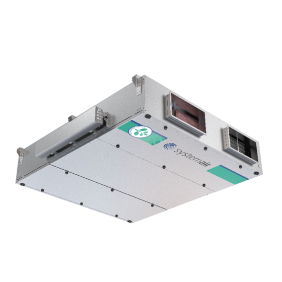
- Page 1 Topvex FC Compact Air Handling Unit Installation instructions Document in original language | 151627 · A002...
- Page 2 © Copyright Systemair AB All rights reserved E&OE Systemair AB reserves the rights to alter their products without notice. This also applies to products already ordered, as long as it does not affect the previously agreed specifications. 151627 | A002...
-
Page 3: Table Of Contents
Contents Declaration of conformity........1 Warnings............2 Product information .........2 General ..........2 Technical data ........3 3.2.1 Dimensions and weight ....3 3.2.2 Space required......4 3.2.3 Electrical data Topvex FC....5 Transport and storage ......5 Installation.............6 Unpacking ..........6 Where/how to install ......6 Condensation drain.........7 Installing the unit........9 4.4.1 Installation procedure.... -
Page 5: Declaration Of Conformity
Declaration of conformity | Declaration of conformity Manufacturer Systemair Sverige AB Industrivägen 3 SE-739 30 Skinnskatteberg SWEDEN Office: +46 222 440 00 Fax: +46 222 440 99 www.systemair.com hereby confirms that the following products: Air handling units Topvex FC02 EL... -
Page 6: Warnings
Product information General This installation manual concerns air handling unit type Topvex FC manufactured by Systemair Sverige AB. The units in- clude the following model options: • Model: Topvex FC02, Topvex FC04, Topvex FC06 • Heating coil: EL (Electric), HWL (Water coil, low power), HWH (Water coil, high power) or None. -
Page 7: Technical Data
Product information | Technical data 3.2.1 Dimensions and weight øK *1/2" Fig. 1 Dimensions Topvex FC02 (mm) drawn as right hand unit * = male connection Model Topvex FC02 1500 2101 1919 1208 1577 1720 øK Model Weight, kg Topvex FC02 151627 | A002... -
Page 8: Space Required
| Product information *1/2" Fig. 2 Dimensions Topvex FC04, Topvex FC06 (mm) drawn as right hand unit * = male connection Model Topvex FC04 2024 2561 1190 1204 2098 2242 Topvex FC06 2214 2546 1182 1208 2288 2432 □ □ K Model Weight, kg Topvex FC04... -
Page 9: Electrical Data Topvex Fc
Product information | 3.2.3 Electrical data Topvex FC Model Fans (W tot.) 230V 1~ and El Heating battery (kW tot.) Fuse (mains) (A) for 400 V 3N~ 230 V 1~ and 400 V Topvex FC02 1040 3x13 Topvex FC02 1040 None, HWL, HWH Topvex FC04 1536... -
Page 10: Installation
Unpacking Verify that all ordered equipment are delivered before starting the installation. Any deviation from the ordered equip- ment must be reported to the supplier of Systemair products. Where/how to install Topvex FC are meant for indoor installation. The electronic components should not be exposed to lower temperature than 0°... -
Page 11: Condensation Drain
Installation | Condensation drain The unit must be connected to the condensation drain. A transition, tube and drain trap are enclosed upon delivery. Connect the drainage on the units exhaust side (pos 2, figure 4). The drainage on the supply side (pos 1) must be con- nected if the unit will be used with cooling equipment or if it will run extensively where the outdoor climate is very hu- mid. - Page 12 | Installation G½" ø32 mm Fig. 4 Drainage connection, right hand unit Table 1 Max. Negative H (mm) pressure (Pa) 1000 Normal conditions 151627 | A002...
-
Page 13: Installing The Unit
Installation | Installing the unit The units are designed for ceiling installation. Left and right connections are possible. Fig. 5 Installing position, left hand unit Fig. 6 Installing position, right hand unit Table 2 Symbol description Symbol Description Supply air Exhaust air Outdoor air Extract air... -
Page 14: Installation Procedure
| Installation 4.4.1 Installation procedure Warning Beware of sharp edges during mounting and maintenance. Make sure that a proper lifting device is used. Use protective clothing. Warning The units electrical connection to the mains power supply must be preceded by an all pole circuit breaker with a minimum 3 mm gap. -
Page 15: Mounting The Sliding Door Kit
Installation | Mounting the sliding door kit A sliding door kit for the inspection doors can be acquired as an accessory and can be mounted on the units. The kit is installed according to below procedure. Warning The door handles are only intended to be used during the installation and service. Handles must be removed before the unit is put into operation to ensure the required level of safety for the unit. - Page 16 | Installation 5 Fasten with BSS screws Fasten the rail to the side of the casing with the en- closed BSS screws. 6 Open hatch Open the hatch by unlocking the inner handles (pos. 1) followed by the outer handles (pos. 2). The hatch can now be pushed toward the centre of the unit.
-
Page 17: Connections
Installation | Connections 4.7.1 Ducting Fig. 8 Connections and basic components in right hand connected units Description Symbol Position Connection supply air Connection exhaust air Connection outdoor air Connection extract air Fan supply air Fan extract air Filter supply air Filter extract air Heat exchanger Electrical connection box... -
Page 18: Condensation And Heat Insulation
| Installation 4.7.2 Condensation and heat insulation Outdoor air duct and exhaust ducts must always be well insulated against condensation. Correct insulation installation on ducts connected to the unit is especially important. All ducts installed in cold rooms/areas must be well insulated. Use insulating covering (minimum 100 mm mineral wool) with plastic diffusion barrier. - Page 19 Installation | Fig. 9 Topvex FC is equipped with a built in regulator and internal wiring (figure 10). Fig. 10 Electrical components Description Position Control unit CU283W-4 Transformer 230/24V AC Terminals for internal and external components Terminals for internal wiring Terminals for power supply to the unit Contactor (K2) On/Off Pump control water (HW units only, not present in EL-units)
-
Page 20: External Connections
| Installation 4.7.5 External connections Table 3 Connections to external functions Terminal block Description Remark Ground Earthed neutral (mains power supply) Used for phase 230V 1~ and 400V 3~ Used for phase 230V 1~ if the Phase (mains power supply) unit has this mains 400V 3~/230V 3~ Phase (mains power supply) -
Page 21: Bms Connection
Installation | 4.7.6 BMS Connection Communication possibilities for control unit. • RS485(Modbus): 50-51-52 or 60-61-62 • RS485(BACnet): 50-51-52 or 60-61-62 • RS485(Exoline): 50-51-52-53 or 60-61-62-63 • TCP/IP Exoline • TCP/IP Modbus • TCP/IP WEB • TCP/IP BACnet RS 485 connection Fig. -
Page 22: Installing Navipad Control Panel
100 meters of cable. 4.8.1 Dimensions NaviPad is the control panel for Systemair´s Air handling units. NaviPad has an easy to understand menu structure and contains 13 languages. c/cD 40,3... -
Page 23: Additional Equipment
Installation | Additional equipment For information concerning additional external equipment such as valve actuators, motorized dampers, roof units, wall grilles etc. see technical catalogue and their enclosed instructions. For electrical connections of external components see enclosed wiring chart. 151627 | A002... - Page 24 Systemair Sverige AB Industrivägen 3 SE-739 30 Skinnskatteberg, Sweden Phone +46 222 440 00 Fax +46 222 440 99 www.systemair.com...
Need help?
Do you have a question about the Topvex FC04 and is the answer not in the manual?
Questions and answers