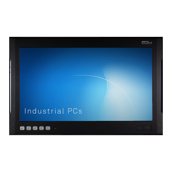
Summarization of Contents
Notes
General Remark
Provides general introductory information about the instruction manual and its purpose.
Limitation of Liability
Details the manufacturer's disclaimer regarding damages from non-compliance or improper use.
Manufacturer
Identifies the manufacturer of the product as ads-tec Industrial IT GmbH.
Relevant Device Documentation
Lists other essential documents for device setup and operation, including website resources.
Safety Instructions
Structure of Safety Instructions
Explains how safety information, signal words, and hazard references are organized.
Graduation of Risk Level
Describes how signal words are used to classify the severity of hazards.
Explanation of Used Symbols
Defines the meaning of safety symbols like DANGER, WARNING, CAUTION, and ATTENTION.
Symbols
Details symbols for battery disposal, electronics disposal, protective earth, and hot surfaces.
Data, Figures and Modifications
States that information is based on current knowledge and subject to change, without liability.
Trademarks
Acknowledges software and hardware trademarks and company brand names.
Copyright
Outlines copyright protection for the manual and restrictions on its use.
Environmental Conditions
Specifies operating and storage temperature, humidity, vibration, and shock resistance limits.
Standards
Declares CE marking and compliance with European Directives for the device.
Scope of Delivery
Lists the components included in the packaging and optional delivery items.
Device Features
Highlights key features like multi-touch, rear service access, and wide-screen format.
Operating and Safety Instructions
Operating Location
Specifies that the system is for switching cabinets and prohibits non-specified environments.
Damage Due to Improper Use
Instructs to shut down the device immediately if signs of damage from improper use are evident.
Warranty / Repairs
States that repairs during warranty must be performed by the manufacturer or authorized personnel.
Intended Use
Defines the Panel PCs for control/monitoring of machines, installed in electrical panels, consoles, or cabinets.
Improper Use
Describes improper use, including applications requiring further approvals or handling damaged devices.
Treatment and Disposal of Lithium Batteries
Provides safety warnings and instructions for handling and disposing of the device's lithium battery.
Safety Instructions
Details safety measures to prevent damage from electrostatically sensitive components during installation/service.
Installation
Installation Option
Specifies that the installation location must be accessible from the rear and details wall thickness requirements.
External Device Dimensions OPC7008
Provides detailed external dimensions and connection port layout for the OPC7008 model.
External Device Dimensions OPC7008
Presents cutout dimensions for the OPC7008 model for installation purposes.
External Device Dimensions OPC7013
Provides external dimensions and connection port layout for the OPC7013 model.
Installation Layout OPC7013
Presents cutout dimensions for the OPC7013 model for installation purposes.
External Device Dimensions OPC7015
Provides external dimensions and connection port layout for the OPC7015 model.
Installation Layout OPC7015
Presents cutout dimensions for the OPC7015 model for installation purposes.
External Device Dimensions OPC7022
Provides external dimensions and connection port layout for the OPC7022 model.
Installation Layout OPC7022
Presents cutout dimensions for the OPC7022 model for installation purposes.
Safety Notices Prior to Beginning Installation
Details safety precautions regarding grub screws for Quick Snap elements before installation.
Order of Installation (OPC7008)
Provides step-by-step instructions for installing the OPC7008 model, including torque specifications.
Order of Installation (OPC7013-7022)
Details the installation steps for OPC7013-7022 models, including mounting cut-out and tensioner fastening.
Commissioning
Available Interfaces (OPC7008)
Identifies and describes the available interfaces and ports on the OPC7008 model.
Available Interfaces (OPC7013-7022)
Lists and describes the interfaces for OPC7013-7022 models, including variations.
Cable Installation
Explains the location of interfaces and power supply plug for cable connection.
Order of Steps During Commissioning
Outlines the sequence of steps for connecting power and data cables during commissioning.
Check for Operational Readiness
Provides instructions on checking for hidden damages and securing the device after commissioning.
Operation
Front Panel Operation Keys (Basic Function)
Explains the functions of the front panel keys and their assignments via a special driver.
Soft Keyboard
Describes the soft keyboard functionality for touch screen data entry and its installation.
Touch Screen
Details the touch screen monitor, its internal connection via USB, and driver availability.
Status Displays
Explains the meaning of different SYS LED states indicating device status (off, ready, volume, brightness).
Interfaces
Voltage Supply 24V DC
Describes the 24V DC power supply connection via a lead-through terminal with screw connection.
USB Connections
Details the pin assignments and compliance for USB 2.0 and USB 3.0 interfaces.
Network Connection (RJ45)
Explains Ethernet network integration using RJ45 connectors for 10/100/1000Mbit standards.
Serial Interface COM (RS232)
Describes the RS232 serial interface for digital data transmission using a 9-pin SUB-D cable.
Drives
Hard Disk / Flash SSD
Lists the available storage options: 2.5" HDD SATA, 2.5" SSD SATA, and mSATA-Form factor SSD.
External Drives
Explains how to connect external storage media via USB interfaces and notes caution for hot-plugging.
Software
Configuration Center
Introduces the Configuration Center software modules provided by ADS-TEC for device configuration.
Service & Support
ADS-TEC Support
Provides contact information and availability hours for the ADS-TEC support team.
Company Address
Lists the company address, telephone number, email, and website for ads-tec Industrial IT GmbH.
Component Replacement
Opening the Service Slot (OPC7008)
Details the procedure for removing screws to open the service slot on the rear of the OPC7008 device.
Opening the Service Slot (OPC7013-7022)
Explains how to remove screws and tilt the rear cover to access the service slot on OPC7013-7022.
Replacing the Lithium Battery (OPC7000 Series)
Provides instructions on how to remove, replace, and install the lithium battery, including type and polarity.
Replacing the HDD (Hard Disk) (OPC7013-7022)
Details the removal and installation procedure for the HDD (hard disk) on OPC7013-7022 models.
Replacing the Fan (OPC7013-7022)
Provides instructions for replacing the fan, including unplugging the fan cable and using a specific screwdriver.
Replacing the Working Memory (RAM) (OPC7013-7022)
Explains how to release and replace the RAM memory modules by pulling retaining clips.
Replacing the mSATA Modules (OPC7000 Series)
Details how to remove the HDD to install or replace mSATA modules, and the mounting procedure.


Need help?
Do you have a question about the OPC7013 and is the answer not in the manual?
Questions and answers