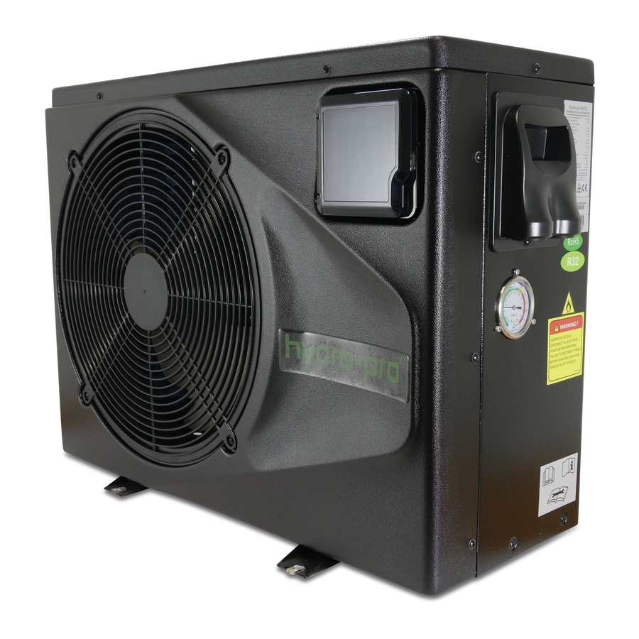
Summarization of Contents
1. PREFACE
Unit Characteristics and Safety Warnings
Highlights key features of the heat pump and provides essential safety warnings for operation and installation.
2. SPECIFICATION
Performance Data for Swimming Pool Heat Pump Units
Details performance metrics like heating capacity, COP, power supply, and noise levels for various models.
Dimensions for Swimming Pool Heat Pump Units
Provides detailed physical dimensions and diagrams for various heat pump models (P6/32, P8/32/P12/32).
3. INSTALLATION AND CONNECTION
Installation Illustration and Steps
Illustrates the plumbing connection of the heat pump to the pool system, including water flow and components.
Swimming Pool Heat Pump Location Requirements
Details optimal placement factors including fresh air availability, electricity access, and piping connections.
Pool Heat Pump Proximity to Pool
Explains the impact of distance from the pool on heat loss and run time, recommending optimal proximity.
Swimming Pool Heat Pump Plumbing
Covers plumbing requirements, pipe types, connection locations, and condensation management.
Electrical Wiring and Initial Unit Startup
Provides guidance on electrical hookup, grounding, bonding, circuit protection, and initial unit startup procedures.
4. Use and Operation Instruction of Wire Controller
Wire Controller Functionality and Layout
Details the layout and functions of the wire controller's display and buttons for unit operation.
Controller Symbols and Meanings
Explains the meaning and function of various icons displayed on the wire controller for different modes and settings.
Controller Usage: Starting, Shutting Down, and Modes
Guides users on turning the unit on/off, switching between operating modes like cooling, heating, and auto.
Temperature and Clock Setting Procedures
Details the process for adjusting target temperatures and setting the clock/timer functions on the wire controller.
Timer Setting and Cancellation
Explains how to set and cancel the timer for the heat pump unit's on and off cycles using the wire controller.
Keyboard Lock and Malfunction Display
Details how to lock/unlock the keypad and describes how malfunction codes are displayed on the controller.
Parameter Table for Controller Settings
Lists adjustable parameters for heating, cooling, and auto inlet target temperatures.
Trouble Shooting Guide
Malfunction Codes, Causes, and Solutions
Provides a comprehensive list of error codes, their causes, and recommended solutions for troubleshooting unit issues.
5. MAINTENANCE AND INSPECTION
Area Checks and Safety Precautions
Ensures the area around the unit is safe, dry, clean, and well-ventilated, with checks for refrigerant and fire extinguishers.
Maintenance Work Procedures and Electrical Safety
Covers maintenance procedures, electrical safety checks, and ensuring component integrity during repairs.
Sealed Components, Cabling, and Leak Detection
Details repairs to sealed components, cabling checks, and methods for detecting refrigerant leaks safely.
Refrigerant Recovery, Evacuation, and Labeling
Outlines procedures for safe refrigerant recovery, evacuation, flushing, and proper equipment labeling.
Decommissioning and Charging Procedures
Specifies essential steps for safe decommissioning, refrigerant charging, and system pressure/leak testing.
6. APPENDIX
Circuit Diagrams for P6/32 and P8/32 Models
Provides electrical circuit diagrams for the P6/32 and P8/32 heat pump models, showing component connections.
Circuit Diagrams for P12/32 and P14/32 Models
Provides electrical circuit diagrams for the P12/32 and P14/32 heat pump models, detailing internal wiring.
Circuit Diagram for P20/32 Model
Provides the electrical circuit diagram for the P20/32 heat pump model, illustrating component connections.
Circuit Diagrams for P23T/32 and P26T/32 Models
Provides electrical circuit diagrams for the P23T/32 and P26T/32 heat pump models, showing component interconnections.
Cable Specifications for Unit Installation
Specifies required cable sizes, MCB ratings, and creepage protectors for single and three-phase units.
Refrigerant Saturation Temperature Comparison
Compares saturation temperatures of R410A and R32 refrigerants at various pressure points.


Need help?
Do you have a question about the P20/32 and is the answer not in the manual?
Questions and answers