Table of Contents
Advertisement
Digitrax Complete Train Control
Starter Set Manual
Includes Instructions for:
DCS100 Command Station Booster
DCS200 Command Station Booster
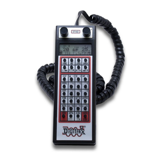
DT402 SeriesThrottles
Duplex Radio Operation with UR92 & DT402D
Simplex Radio Operation with UR91 & DT402R
Infrared Operation with UR90 & DT402
Walkaround Operation with UP5
2443 Transmitter Road
Panama City, Florida USA 32404
(850) 872-9890 Fax (850) 872-9557
Digitrax Manuals & Instructions are updated periodically.
Please visit www.digitrax.com for the latest version of all
manuals & for available firmware updates.
This rev 2.0 manual was updated 07/09.
Super Premium
Digitrax, Inc.
www.digitrax.com
C
omplete
T
rain
C
ontrol
Advertisement
Table of Contents
Troubleshooting

Related Manuals for Digitrax Super Chief Xtra DT402R


Summary of Contents for Digitrax Super Chief Xtra DT402R
- Page 1 Panama City, Florida USA 32404 (850) 872-9890 Fax (850) 872-9557 www.digitrax.com Digitrax Manuals & Instructions are updated periodically. Please visit www.digitrax.com for the latest version of all manuals & for available firmware updates. This rev 2.0 manual was updated 07/09.
-
Page 2: Introduction
The Digitrax system reduces and simplifies layout wiring for new layouts. If you already have a layout, you probably won’t need to rewire to install Digitrax. Your Super Chief Xtra Starter Set has several components: •... -
Page 3: Table Of Contents
4.9 Quick Start Problems?...............19 4.10 What’s Next? .................20 5.0 LocoNet: The Digitrax Difference! ....21 5.1 System Architecture .................21 5.2 Event Driven or Polled? ..............21 5.3 Network Speed ..................22... - Page 4 6.5.2 Short Circuits ................30 6.5.3 To set up power districts and sub-districts on your layout:..30 6.5.4 How can I be sure I have enough power to run my trains? ..30 6.6 Adding a DB150 Booster ..............30 6.7 Reversing Section Wiring ..............31 6.8 Using a DB150 as an AutoReversing Booster ........32 6.9 Using PM42 for Power Management and AutoReversing....33 6.10 Using AR1 for AutoReversing ............33...
- Page 5 10.3.8 Function Display...............53 10.3.9 Track Power Indicator...............53 10.3.10 Tetherless Indicator..............53 10.3.11 L and R Semaphores-Cab Signaling........53 10.4 DT402 Keypad ................54 10.4.1 FUNC Key ................54 10.4.2 MU Key ..................54 10.4.3 LOCO Key................54 10.4.4 SWCH Key ................54 10.4.5 L and R Reverse Keys ..............54 10.4.6 Y / + and N / - Keys..............55 10.4.7 DISP Key ..................55 10.4.8 PROG Key ................55...
- Page 6 15.4.1 Enabling Routes ...............83 15.4.2 External Routes.................83 15.4.3 Edit Routes ................84 15.5 FIND Key and Digitrax Transponding..........86 16.0 Customizing Your Throttle - Step-by-Step ...87 16.1 Changing the Throttle Options............87 17.0 Programming Configuration Variables (CVs) ..90 17.1 Programming Mobile Decoder Addresses ........91...
- Page 7 19.0 Decoder Status ....... . .98 19.1 Status Editing a Decoder ..............98 19.2 Note for Non-Digitrax Decoder Users ..........99 20.0 UR92 Additional Information .
-
Page 8: Super Chief Xtra Quick Start Guide
U N I V E R S A L P A N E L U P 5 U N I V E R S A L P A N E L U P 5 Command Station. Any Digitrax Command Station can be used. D T 4 0 2 D T 4 0 2 2. -
Page 9: Connect The Dcs100 To The Power Supply
” LED will come on. POWER ON 1.2 Connect Your DT402 Series Throttle to the DCS100 1. Plug the DT402 series throttle into the LocoNet jack on your Digitrax “A” Command Station. Make sure the power supply is connected to the com- mand station. -
Page 10: Super Chief Xtra Quick Start Duplex Radio Operation
2.0 Super Chief Xtra Quick Start Duplex Radio Operation These instructions will get you up and running in duplex radio mode in just a few minutes! A full description of all controls and technical reference informa- tion are included later in this manual. 2.1 Install the UR92 The UR92 Duplex Radio Transceiver/IR Receiver is simple to install and begin using on your layout. -
Page 11: Join Your Dt402D Throttle To A Duplex Group
That is all that is required for UR92 installation! You are now ready to join a Duplex Group with your DT402 Duplex Throttle! See UR92 installation guide for additional information on setup and troubleshooting 2.2 join Your DT402D Throttle to a Duplex Group The following ‘plug-in’... -
Page 12: Dt402 Installation
3.0 DT402 Battery Installation Back of Remove Throttle battery cover by pressing here Battery Battery Compartment Cover and then sliding Correct installation the cover toward 9 Volt orientation for the bottom of Battery+ powering the throttle the case. Storage orientation 9 Volt (Polarity Reversed) Battery... -
Page 13: Additional Quick Start Basics
4.0 Additional Quick Start Basics 4.1 DT402 Throttle Start Up 1. Plug the DT402 throttle into any throttle jack on a functioning Digitrax LocoNet System or other LocoNet compatible system and you are ready to get started! See picture in Section 1.0 2. -
Page 14: Dt402 Series Throttle Keyboard Layout
4.2 DT402 Series Throttle keyboard Layout Infrared Flashlight LCD Display LEDs L Throttle R Throttle Knob Knob FUNC Key LOCO Key Press once to change Press to enter to Fn (function) mode address selection mode. MU Key Press again to Press to enter select address. -
Page 15: Dt402 Series Throttle Controls At A Glance
4.3 DT402 Series Throttle Controls At A Glance R Throttle L Throttle Speed Speed Address Address Direction Direction Blinking Smoke Icon indicates that the R Throttle is active. Functions displayed correspond to the active throttle 1. The DT402 handheld has two knobs called the and the L Throttle (Left) . -
Page 16: Track Power On And Off
4.4 Track power on and off indicator on your DT402/D and indica- TRACK POWER TRACK STATUS tor on your DCS100 command station show whether track power is on or off. The first time you plug in your throttle, track power will usually be off. Before you can run trains, you will need to turn on the track power. -
Page 17: Select And Run An Analog Loco On Address "00
4.5 Select and Run An Analog Loco on Address “00” 1. Place an analog locomotive (one without a decoder) on your layout. While the analog loco is sitting still, you will hear the characteristic “singing” caused by the DCC track signal when it is applied to analog locomotives. Once the analog loco is moving, this sound will change and be less notice- able. -
Page 18: Select And Run A Decoder Equipped Loco
Each decoder has an address. To select a decoder equipped locomotive and run it on a throttle, you must know its address. Digitrax decoders are set up at the factory with the “default” 03. This means that when you take a Digitrax decoder out of the package and install it in your loco, you can select address 03 on your throttle and run the decoder. - Page 19 The illustration below shows the display after address is selected on the “00” and address is selected on the , We see the R Throttle “03” L Throttle TRACK in the top line, the speed bar graphs at 0 speed and the POWER Indicator On text area also at 0 speed for both throttles.
-
Page 20: Shutting Down The System
If that does not work or if you have other questions or problems, we encourage you to call, fax or e-mail Digitrax or your favorite dealer. The Digitrax Tech Support Depot is always available at www.digitrax.com/help There are thousands of successful Digitrax installations around the world and we want to be sure that yours is one of them. -
Page 21: What's Next
Your Super Chief Xtra Set is the gateway to all the pos- sibilities and options offered by Digitrax so the best advice is to take it step by step and don’t try to do everything at once. For additional resources check out... -
Page 22: Loconet: The Digitrax Difference
DCC, such as detection systems and transponding, are not standardized. LocoNet is a hybrid system that incorporates DCC and other technologies to expand the capabilities of your system. Your Digitrax system gives you the best of both worlds with a system that is compatible with today’s DCC standards and also goes beyond those standards to deliver enhanced sys- tem performance and advanced features that are far beyond the scope of DCC. -
Page 23: Network Speed
5.3 Network Speed Is faster network speed better? Not necessarily, it depends on whether the system uses event driven or polled architecture. The NMRA’s track control packet for- mat sets the “speed limit” for all DCC systems. Going faster than the “speed limit”... - Page 24 Power District (Double Gapped) Personal Computer (optional) Power Supply D B 1 5 0 D B 1 5 0 L O C O N E T L O C O N E T S C A L E S C A L E M O D E M O D E 6 pin "T"...
-
Page 25: Loconet Wiring Components
Making your own LocoNet Cables is simple and cost effective. We recom- mend that you invest in a good quality set of crimpers. Most Digitrax dealers can supply or tell you where you can get the cable, plugs and crimpers you will need. -
Page 26: Loconet Throttle Jacks And Loconet Connection Jacks
5.10 Installing the Universal Panel (UP5) The Digitrax Universal Panel UP5 or UR92, included with your Super Chief Xtra Starter Set, provides a simple plug and play alternative to wiring RJ12 telephone style jacks around the layout. This fascia mounted panel provides 2 RJ12 LocoNet throttle jacks as well as a “... -
Page 27: Hooking Up The Up/Ur's Track Status Indicators (Optional)
+12V Jacks 2 mm power jack to +15V DC (NOT connected center positive Throttles to DC power) (for example, RJ12 Screw Digitrax PS14) TelCo Terminals Jacks For Local Track Power LocoNet Connection 2 mm power Connections jack (connected Wire together small holes... -
Page 28: Advanced Installation Of Digitrax On Your Layout
Early proponents of DCC touted the fact that you can hook up your railroad with just two wires. While this is technically correct, there are some things you will need to consider to get the most out of Digitrax Complete Train Control. -
Page 29: Service Mode Programming (Using A Programming Track)
Programming Track With DCS100 6.2 Direct Home Wiring vs. Common Rail Wiring Digitrax strongly recommends direct home wiring where each power district and its booster are electrically isolated. This type of wiring is safer and more convenient to work with for debugging and for adding reversing sections and detection later. -
Page 30: Recommended Wire Sizes For Power Bus And Track Feeders
6.3 Recommended wire sizes for power bus and track feeders On an average size layout Digitrax recommends that the power bus from the booster be at least 16AWG. When feeding areas up to 50’ from the booster, we recommend using 12 AWG wire for the power bus. -
Page 31: Number Of Locos
2. Double gap the rails at each end of the power district and single gap for sub-districts within districts. 3. Connect a DCS100 or other Digitrax booster and power supply to each dis- trict. Use a PM42 with your DCS100s to set up sub-districts. -
Page 32: Reversing Section Wiring
6.7 Reversing Section Wiring You can operate reversing sections manually or automatically with Digitrax Complete Train Control using an auto-reversing booster, a reversing section controller such as an AR1 or PM42. You must double gap (completely isolate) -
Page 33: Using A Db150 As An Autoreversing Booster
automatic reversing will not cause analog(non decoder equipped) locos to auto reverse. If you choose manual operation, use a DPDT switch or relay to handle the polarity change as the loco enters and leaves the reversing section. If you choose to use a DB150 auto reversing booster to completely automate the reversing section, power the reverse loop with a DB150 and power supply and the main layout with your DCS100 and power supply. -
Page 34: Using Pm42 For Power Management And Autoreversing
If you are using two Digitrax boosters, one acts as the polarity reference and the other handles the polarity reversal for the reversing section. You can also use a DCS100 and PM42 to handle automatic reversing sections. -
Page 35: Troubleshooting Layout Wiring
Digitrax equipment from the layout and test it on a small section of track not connected to the layout to confirm that the problem is not with your Digitrax equipment. -
Page 36: Dcs100/200 Control Panel
Digitrax recommends the PS515 power supply to power all DCS100s and the PS2012 for DCS200s. There are many other power supplies and power packs that can supply the input power for the DCS100. Check with your Digitrax dealer for suggestions. Most regular DC model railroad power packs are not able to supply 5 amps to the DCS100 booster, because they were designed to run only 1 or 2 locomotives in a DC blocked system. -
Page 37: Prog A And Prog B Terminals
7.5 RAIL B and RAIL A Terminals Connect these terminals to the track on all Digitrax boosters and command sta- tions. If you are using more than one booster, always connect the same rail to... -
Page 38: Track Status Indicator
DCS100 may be OFF. 7.7 LOCONeT jacks A and B These jacks let you expand your Digitrax system by simply plugging LocoNet devices in to the system. They can be used for throttles and other LocoNet devices. These jacks are functionally the same and can be used interchange- ably. -
Page 39: Mode Switch
from either the terminal to the green ground wire on the RAIL A RAIL B case. Multiply the measured voltage by 2 to determine the approximate digital track voltage supplied. 7.9 MODe Switch switch settings are: MODE normal operations. customize the DCS100 by changing its option switch settings. shutdown the system and all throttles that are plugged in to the SLEEP system. -
Page 40: Net Indicator
DCS100. This indicator should be steady green blinking off briefly once every 4 seconds. This indicates that the setting for DCS100 Option Switch 05 is set up correctly. If you see 8 blinks every 4 seconds then we recommend that you change the DCS100 Option Switch 05 to “closed.”... -
Page 41: Dcs100 Audible Sounds
7.13 DCS100 Audible Sounds The DCS100 uses several beeps and clicks that can be used as diagnostic tools that help you debug a number of conditions Sound Meaning DCS100 has powered on successfully or has sent a 1 Beep programming command. A loco address has been "purged"... -
Page 42: Dcs100 Cmos Battery Replacement
8.0 DCS100 CMOS Battery Replacement When you hear 7 beeps when power is applied to your DCS100, you need to replace the CMOS battery. The DCS100 will continue to operate, even if this battery is not present, but all your memory settings and option switch settings will not be remembered when the DCS100 is powered down. -
Page 43: Customizing Your Dcs100/200--Option Switch Setup
9.0 Customizing Your DCS100/200--Option Switch Setup The following instructions apply to both the DCS100/DCS200 Command Stations/Boosters. We will refer to the DCS100 in all instructions, but they apply to the DCS200 also. The Option Switch (OpSw) setup allows you to customize the operation of the units to meet your layout and operation. -
Page 44: Dcs Option Switch Tables
7. Use the key to set the OpSw to (closed) or the key to CLOC / c OPTN / t set the OpSw to (thrown). In the example above we have changed OpSw 5 from its factory setting of (recommended setting). 8. - Page 45 DCS Option Switch Tables Option Factory effect on System operation when "closed" Switch # Default OpSw 01 Do Not Change OpSw 02 Do Not Change (“c” setting makes DCS100 a booster) OpSw 03 DCS100's booster is auto reversing OpSw 04 Do Not Change Command station master mode OpSw 05...
- Page 46 Option Factory effect on System operation when "closed" Switch # Default OpSw 21 OpSw 21-23 set the global system default type for "NEW" loco selections. SW21/22/23 set as follows: t-t-t = 128 step mode OpSw 22 t-t-c = 128 step FX mode c-t-t = 14 step mode c-c-t = 28 step OpSw 23...
- Page 47 Option Factory effect on System operation when "closed" Switch # Default Disable LocoNet update of command station’s OpSw 43 track status Expand slot refresh area from 22 (Big Boy compatible) OpSw 44 to 120 OpSw 45 Disable reply for switch state request OpSw 46 Do Not Change Program track is brake generator when not program-...
- Page 48 Infrared Flashlight LCD Display LEDs L Throttle R Throttle Knob Knob FUNC Key LOCO Key Press once to change Press to enter to Fn (function) mode address selection mode. MU Key Press again to Press to enter select address. consist mode SWCH Key L Reverse Key Press to enter...
-
Page 49: Dt402 Series Throttle Control Panel
10.0 DT402 Series Throttle Control Panel 10.1 General Information The DT402 series are full function hand held throttles that include 2 indepen- dent throttles and a common keypad to control, up to 29 functions (F0-F28), turnouts and programming. The DT402 does not require a battery in normal walkaround operation. -
Page 50: Liquid Crystal Display (Lcd)
10.3 Liquid Crystal Display (LCD) Functions 0-12 (Active Throttle) L Bar Graph R Bar Gragh Tetherless Indicator Track Power Indicator L Semaphore R Semaphore Text Area R Smoke Icon L Smoke Icon L Loco Icon R Loco Icon Mode L Throtte Direction R Throttle Direction Indicator Indicators... -
Page 51: Mode Indicator
at a time can have access to the keypad and function controls. The active throt- tle has access to the function controls and the status of the functions for the active throttle are displayed in the top line of the LCD. To make either throttle the active throttle simply click it once or turn the Throttle knob a little. -
Page 52: Text Area
Power Turn track power on and off Change locomotive speed steps to 14, 28, or Status Edit 128 as needed Programming Paged-Digitrax preferred method Programming Physical Register Programming Direct Operations Mode (Ops Mode) programming Programming on the mainline. -
Page 53: L (Left) And R (Right) Throttle Display
10.3.6 L (Left) and R (Right) Throttle Display The decoder address selected on the is displayed on the bottom line L Throttle of the LCD to the left of the Mode Indicator. The decoder address selected on is displayed to the right of the Mode Indicator. The address can R Throttle show as either the 2-digit or the 4-digit decoder address. -
Page 54: Function Display
The L and R Semaphores are used when cab signaling is implemented on the layout. More information about signaling and detection will be avail- able on our web site, www.digitrax.com, as these products become available. Information on how to activate these indicators will be included in the manuals for our detection and signaling products. -
Page 55: Dt402 Keypad
these features in their software. The L and R Semaphores will display the following: = Clear = Approach = Stop 10.4 DT402 keypad 10.4.1 FUNC key key is used to enter function control mode. Function control FUNC mode is the default mode for normal locomotive operation with the FUNC FUNC DT402. -
Page 56: Y / + And N / - Keys
FIND FIND FIND Digitrax Transponding and locos or cars equipped with transponders to find the location of those pieces of rolling stock on the layout. 10.4.11 BACk key key is used to go back one step. -
Page 57: Pwr Key
10.4.12 PWR key key is used to enter power mode for turning layout power on and off. Once you press this key, you will be prompted to use the Y / + key to turn power on or the key to turn power off. N / - key is also used to turn on and off the flashlight feature. -
Page 58: Full Numeric Keypad
return locos to their speed prior to the EMRG STOP. Press key to leave eXIT mode and return to mode after turning track power back on with key and key. Y / + 10.4.18 Full Numeric keypad The numeric keys on the keypad are usually related to the throttle mode shown in the LCD’s mode indicator area. -
Page 59: How To Select And Run Trains
11.0 How to Select and Run Trains 11.1 Turn track power on and off indicator on your DT402 display shows the track power TRACK POWER status. There is also a LED on your Command Station. If the TRACK STATUS indicator is lit then track power is on. To turn the track power TRACK POWER on or off: 1. -
Page 60: Select And Run An Analog Loco On Address "00
DCC track signal when it is applied to analog locomotives. Once the analog loco is moving, this sound will change and be less notice- able. (Digitrax recommends that analog locos not be left sitting on DCC powered track for long periods of time when they are not running.) 2. -
Page 61: Select And Run A Decoder-Equipped Loco
Each decoder has an address. To select a decoder-equipped locomotive and run it on either throttle, you must know its address. Digitrax decoders are set up at the factory with the “default” 03. This means that when you take a Digitrax decoder out of the package and install it in your loco, you can select address 03 on your throttle and run the decoder. - Page 62 The illustration below shows the display after address is selected on “00” and address is selected on the , We see the R Throttle “03” L Throttle in the top line, the speed bar graphs at 0 TRACK POWER On Indicator speed and the text area also at 0 speed for both throttles.
-
Page 63: Releasing An Address From A Throttle
11.4 Releasing An Address From A Throttle When you are finished running a locomotive address, release if from your throttle so that it is available for other throttles to select and run. Simplex Radio and Infrared Throttles must be plugged in to LocoNet to release an addresses from your throttle. -
Page 64: Recall A Loco
11.6 Recall a Loco Your DT402 stores the last 4, 8, or 16 unique loco addresses used by the throt- tle in a recall stack. Your DT402 defaults to a 4-address recall stack. See Customizing Your Throttle Section 15.0 for information on how to change the recall stack depth. -
Page 65: Slot Following
3. The DT402 will display in the text area if the loco can be “Steal?=Y” stolen. 4. Press key if you want to steal. Y / + 5. Press (or any other key) if you do not want to steal. N / - Once a throttle has “stolen”... -
Page 66: Stop
12.0 Stop 12.1 Setting A Loco to Zero Speed Turn the Throttle Knob that the loco address is selected on counterclockwise until the speed display shows 00 and the loco stops moving. This lets you slow down your loco and stop it prototypically. If you have set up deceleration for the loco and you move the throttle knob to 0% speed, your loco will slow down and come to a stop at the programmed deceleration CV value. -
Page 67: Controlling Functions
13.0 Controlling Functions The DT402 Throttle will control up to 29 (F0-F28) functions when operating in walkaround and radio mode. When operating in IR mode the DT402 throttles will control up to 9 functions (F0-F8). The numeric keypad is always active in the normal operation mode. -
Page 68: Controlling Expanded Functions F13-F19
Functions 1, 3, 4, 5, 6, 7, 8, 9, 10, 11, and 12 Press the button on the numeric keypad that corresponds with the function number you want turn on/off. The top line of the display will display the num- bers of the functions that are on for the active loco address. -
Page 69: Controlling Functions 20-28
13.3 Controlling Functions 20-28 1. While holding the key down, press the 2 Key then release both FUNC keys simultaneously. The throttle will go into the ‘+20’ mode and display will show the following: 2. Select the second digit from the throttle’s numeric keypad and you’re done. Example: So if you want to turn on function 27, just hold the FUNC down while pressing the... -
Page 70: Tetherless Operation
14.0 Tetherless Operation 14.1 General Tetherless Operations All DT402s can operate with out plugging in to LocoNet. This allows you to disconnect from the LocoNet and still control your locomotives while walking around your layout. The DT402/402R/402D are all “InfraReady.” All come with IR LEDs that send infrared signals to the layout. -
Page 71: Multiple Unit Operations
throttle will be released immediately and that throttle will become inactive. To re-select this loco address plug your DT402/R in to LocoNet and select the loco address on the throttle. 14.1.3 Multiple Unit Operations Consists must be assembled and broken up while the DT402/R is plugged in to LocoNet. -
Page 72: Using The Dt402 Series Throttle In Ir Mode
4. Plugging the throttle into LocoNet will also unlock the throttle. 14.2 Using the DT402 Series Throttle in IR Mode 1. For Infrared operation, plug in at least one Digitrax IR receiver (UR90, UR91 or UR92) to your working LocoNet. Because infrared signals are line of sight, more than one receiver may be necessary for optimal perfor- mance in your layout room. -
Page 73: Loconet Id Change
happens when the throttle “pings” the system to let the command station know that it is still part of the system. This keeps the system from releas- ing that locomotive back to the system and making it available to be select- ed by another throttle. -
Page 74: Using The Dt402R In Simplex Radio Mode
LocoNet ID before beginning operations. 14.3 Using the DT402R in Simplex Radio Mode 1. For Radio operation with the DT402R, plug in at least one Digitrax Simplex Radio receiver UR91 to your working LocoNet. Most layouts only need one UR91. See the manual with your wireless receiver for more information about installing UR91s on your layout. -
Page 75: Using The Dt402D Throttle In Duplex Radio Mode
happens when the throttle “pings” the system to let the command station know that it is still part of the system. This keeps the system from releasing that locomotive back to the system and making it available to be selected by anoth- er throttle. -
Page 76: Configuring The Duplex Group Name
3. Press the key to change the Channel up or down. At each Y / + N / - channel the display will show to search for a Duplex Group name “hit Find” operating on that channel. 4. When the DT402D discovers a Duplex Group the name will blink in the display. -
Page 77: Configuring The Duplex Group Channel (11-26)
14.4.3 Configuring the Duplex Group Channel (11-26) The UR92 ships from the factory with the default Duplex Group default radio channel set to 11. You can select channels 11 through 26 for the radio channel. 1. Plug a DT402D throttle into the UR92. 2. -
Page 78: Advanced Operations Capabilities
The TOP locomotive does not have to be a physical loco on the track, it can be a phantom. Digitrax defines the TOP loco as the loco on the R Throttle Knob at the time when the MU add is performed. - Page 79 5. Press the key, the display will show the following: mode indicator on the display is lit. The loco address in the side of the display will blink to show that it is the address that will be consisted to the address on the R Throttle 6.
-
Page 80: Removing A Loco From A Consist
15.1.2 Removing A Loco From A Consist DT402R and DT402 throttles must be plugged into LocoNet to remove loco addresses from consists. A DT402D may perform this without plugging in. 1. Select the loco address that you want to remove from a consist on the L Throttle 2. -
Page 81: Sw (Switch) Mode
15.2 Sw (Switch) Mode Switch mode is used for sending commands to accessory decoders and for changing option switches in your LocoNet system. The most common use of switch mode is for operating turnouts. When you enter Switch mode, the throt- tle knobs and direction keys will continue to control the loco addresses running on the throttle. -
Page 82: Fast Clock
The DT402 throttle can edit system functions like the fast clock and routes. Both of these features can be enabled or disabled by your command station. Digitrax command stations ship with fast clock enabled and routes disabled. 15.3.1 Fast Clock Basics Many operators use a fast clock during operating sessions to simulate prototyp- ical operations. -
Page 83: Stop The Fast Clock
15.3.2 Stop the Fast Clock Setting the clock rate to 00 will stop the fast clock for the entire system at the currently displayed time. Fast time will re-start when a new non-zero rate value is set. The current fast clock time, fast clock rate and the DT402 alarm time can be changed by using the Edit mode. -
Page 84: Route Basics
15.4 Route Basics You can use your DT402 with a DCS100 to set up routes that are triggered by operating a single turnout address to make it either (closed) or (thrown). Setting up and operating routes is similar to consisting locomotives because you can cause more than one unit to operate based on a single command sent to the system. -
Page 85: Edit Routes
15.4.3 edit Routes To go to the Edit Routes mode you must pass through the clock editor: (Er) 1. Start in Fn mode. Press the key to enter Edit Mode. eDIT Press the key again to enter (Edit Clock) mode. eDIT Press the key again to enter... - Page 86 4. Press the key and in the text area will begin to flash, use the eNTeR “Sw” knobs to dial up the turnout address you want to add to the route. Throttle Use the knob for 100s and the knob for 10s and 1s. L Throttle R Throttle Once you make changes to the turnout address number or the position of...
-
Page 87: Find Key And Digitrax Transponding
15.5 FIND key and Digitrax Transponding On layouts set up for Digitrax transponding with transponders in locos and rolling stock and transponder receivers installed on the layout, the DT402’s key is used to turn on the find command. This lets you see the zone loca- FIND tion of transponders on the layout in your throttle display. -
Page 88: Customizing Your Throttle - Step-By-Step
16.0 Customizing Your Throttle - Step-by-Step 16.1 Changing the Throttle Options You can change the option settings for each DT402 throttle to customize the way it operates. Option setting changes can be made on your DT402 either tethered into the LocoNet for power or untethered with a battery installed. Following the instructions on accessing the Options menu is a chart listing, in menu order, the Option name as it appears in the DT402 display, a brief description of the Option and the factory default for each. - Page 89 Options DT402 Description (Default Option Screen Setting in Bold) On enables IR mode when disconnected IR mode and IR receiver detected on LocoNet RF1 mode On enables Simplex radio (for DT402R) On enables clicking when making any key- Clicks pad or knob changes Fclock On enables Fast Clock i center display 12HrClock...
- Page 90 Options DT402 Description (Default Option Screen Setting in Bold) On enables white flashlight LED to blink DplxBad when repeated Duplex radio messages fail. On enables maximum Duplex power saving. DxRxLPwr Disables slot follwoing updates. On allows throttle to overide command sta- NewTypes tion new- type loco speed step settings 128 speed step setting...
-
Page 91: Programming Configuration Variables (Cvs)
Each of these CVs can be set up when your command station is in the programming mode. The CVs are remembered in the decoder until it is repro- grammed to with a different CV value. Please refer to your Digitrax Mobile Decoder Manual for a complete listing of the CVs supported by each decoder. -
Page 92: Programming Mobile Decoder Addresses
Press the key to cycle through the following PROG options: = Paged mode (Digitrax Preferred Programming Mode) = Physical register mode = Direct mode = Operations mode (See your Command Station manual). 3. After a few seconds, the display will display the last CV and CV Value you programmed. - Page 93 Digitrax Paged decoders when using service mode on the programming track. If you are using non-Digitrax decoders you can change to another mode if they are not capable of Paged mode. 6. To program a 2-digit address, use the...
-
Page 94: Programming Cvs Other Than Addresses
CV and CV Value you programmed. In the case below, it is the last loco address 3. Select the programming mode you wish to use by pressing the PROG until the method you want appears in the Mode Indicator. Digitrax recom- mends using the , or mode for programming Digitrax decoders Direct when using service mode on the programming track. -
Page 95: Operations Mode Programming
5. Press the to activate the CV value. You will see the icon dis- R Throttle played on the right of the DT402 display when you are entering CV Values. Use the to dial up or the keypad to enter the CV value R Throttle you want. -
Page 96: Busy Or Fail Message
When you enter programming mode with a DT402R, Ops mode is the only programming mode that will be available unless you plug in to LocoNet. How to use Operations Mode Programming 1. Select the loco address that you want to program on either the . -
Page 97: Reading Back Cv Values Programmed
1. Place the decoder-equipped locomotive you want to program on the pro- gramming track. You can also do an ops mode read back with Digitrax transponding decoders if you have a LocoNet device that allows ops mode read back plugged in to LocoNet. -
Page 98: How The Dcs100 Manages Addresses
6. To read back any other CV start at (Use the knob to AD2=??? L Throttle dial in Ad2 on the left side of the display or if you were in four digit addressing, press the R throttle knob once). Use the knob to dial L Throttle up the CV you want to read back or use the numeric keypad to enter the... -
Page 99: Decoder Status
Status editing is used most often when you are running non-Digitrax decoders that do not have 128 speed step capabilities. If you can’t get a non-Digitrax decoder to work on your layout and you are sure you are using the correct address for the decoder, you probably need to status edit it to run in 14 or 28 speed step mode. -
Page 100: Note For Non-Digitrax Decoder Users
If you have a decoder that does not have advanced 28/128 speed step mode available, you must “status edit” that locomotive to standard 14 speed step mode before running it with your Digitrax system. Changing the decoder’s sta- tus will cause the system to handle this decoder as a 14 step decoder. Status editing does not reprogram anything in the decoder. -
Page 101: Troubleshooting Ur92 Installation
16 channels to find one that gives the best coverage. See additional resources at www.digitrax.com. There are additional utilities to let you scan the layout environment for any signals using the installed UR92’s as scanners and to easily update your Duplex Group name, channel... -
Page 102: Resetting Ur92 To Factory Defaults
the layout and check Duplex operation for adequate signal coverage. Depending on the layout size, geometry and surrounding materials it is often possible to move the UR92(s) to better cover dead spots. Experimenting with UR92 location will usually help you locate a position that is best for your lay- out. -
Page 103: Runaway Train Or Layout
21.2 Runaway train or layout! • Press the key followed by the key, OR N / - • Flip the switch to on the DCS100 Command Station. MODE “SLEEP” Either way, the layout will stop to give you a chance to regain your composure. To resume operations where you left off •... -
Page 104: The Lt1 Tester
Do the settings in CV29, the configuration register, match the com- mand station output? If your decoder is a 14-step decoder running on any Digitrax system using fac- tory defaults, status editing will be needed for that decoder. See Section 19.1. -
Page 105: Glossary
Active throttle: Digitrax DT throttles are actually two throttles in one. Each handheld can control two different addresses or consists at a time one on the right side or R Throttle and the other on the left side or L Throttle. The DTs display is shared by the two sides of the throttle. - Page 106 Analog Mode Conversion: When a Digitrax decoder does not see DCC pack- ets on the layout it changes automatically to DC operation. Not all DCC sys- tems support this feature so you may have to program non-Digitrax decoders to operate on analog layouts. Automatic analog mode conversion can be disabled by programming CV29.
- Page 107 1. Whether the decoder uses standard 14 speed step mode or advanced 28/128 speed step mode 2. Whether or not the decoder will automatically convert to DC operation when no DCC signal is present. 3. In the case of Digitrax FX decoders, the normal direction of locomo-...
- Page 108 tive travel 4. Whether the decoder uses loadable speed tables and 5. Whether the decoder uses the 2 digit address or the 4 digit address. Configuration Variables (CVs): these are special storage locations or “pigeonholes” in your decoders. By programming values into various CVs, you can control each decoder’s performance characteristics.
- Page 109 Decoder Status: the Digitrax command station assigns each decoder a status based on whether it is new to the system, in-use on a throttle, common in the system and available for selection or idle.
- Page 110 CV29 to enable it. This allows you to enable and disable the table at will and to keep the table stored even when it is not in use. Digitrax FX and 4th generation decoders go one step further and give you 128 speed step resolution with load-...
- Page 111 (CV04) of your locos to simulate the weight and braking char- acteristics of the train to compensate for changing the number of cars and power units in the train. Paged Programming: Digitrax preferred method of service mode program- ming. Physical Register Programming: A primitive type of service mode program- ming.
- Page 112 Recall stack: Digitrax Release: Refreshed (Data): Digitrax command stations re-send data to decoders many times to be sure that the signal is not lost and that you have reliable operation. All in-use and common locos in the system will continue to be refreshed until they become idle.
- Page 113 Status Editing Decoders: a DCC decoder’s status can be manually changed by a Digitrax command station at any time the decoder is selectable. Stealing a Loco: overriding the in-use interlock and forcing the throttle to select an in-use loco. This can result in having two throttles logged on to and controlling one address.
- Page 114 Transponding: The use of transponders installed in rolling stock and transpon- der detectors installed in the layout to allow the system to determine the loca- tion of a particular piece of rolling stock on the layout. Other information about the rolling stock such as speed, direction, etc. can also be determined. Transponding is useful for automation of staging yards, dispatching and for realistic sound systems.
-
Page 115: Fcc Information
• Consult the dealer or an experienced radio/TV technician for help. Note that any modifications to the equipment not expressly approved by Digitrax voids the user’s authority to operate under and be in compliance with CFR 47 rules, as administered by the Federal Communication Commission. -
Page 116: Warranty And Repair Information
Digitrax products. That’s it! Simple, straightforward warranty, no tricky language! All warranties on Digitrax products are limited to repair or replacement of Digitrax products at the discretion of Digitrax. Except to the extent expressly stated, there are no warranties, express or implied, including but not limited to any warranties of merchantability or fitness for a particular purpose. - Page 117 INDeX 2-digit address 53, 94, 98, 104 Decoder Address 27, 28, 53, 111 4-digit address 53, 93, 94, 98, 104 Decoder Status 52, 100, 108 Decoder Won’t Respond 103 Direct Home Wiring 28, 106, 108 acceleration 96, 103, 104 Direct mode 93, 95, 98 address 00 16 Direction 8, 14, 16, 18, 49, 79, 107, analog locomotive 8, 16, 27...
- Page 118 Nested Consisting 81 Resuming your session 19 Network Speed 22 Reverse Key No tetherless release allowed 70 reversing section 28, 31, 105 non-Digitrax decoder 94, 100, 101, Route 85, 86, 111 RUN 19 Numeric Keypad 58 Safety Selection 70 SEL Message 17...
- Page 119 Strange” Locomotive Lights 103 Sw (Switch) mode 43, 82, 85 switch decoder address 82 System Architecture 21 t 43, 112 Testing LocoNet Cables 24 tetherless release 70 Tetherless release allowed 70 Text Area 52 Throttle 14, 49 throttle ID 91 Throttle Jacks 25 Throttle Knobs 49 thrown 82, 112...
Need help?
Do you have a question about the Super Chief Xtra DT402R and is the answer not in the manual?
Questions and answers