Advertisement
UP7
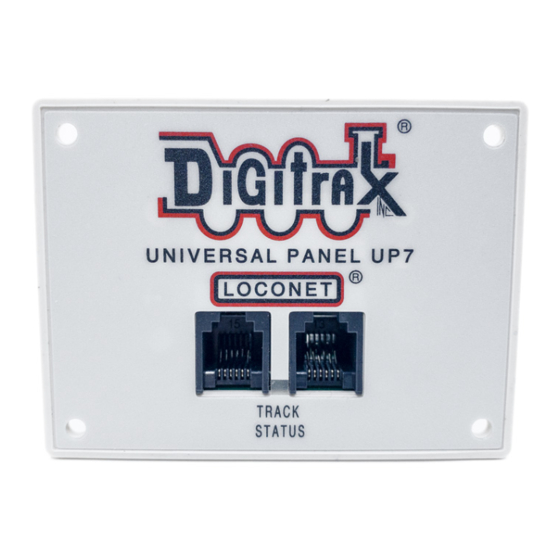
LocoNet Universal Panel
Features:
▪
Simplifies hookup, maintenance and troubleshooting of LocoNet.
▪
All connections plug-detachable.
▪
Two RJ12 Throttle Jacks in front panel.
▪
One RJ12 LocoNet Jack on side of panel.
▪
Track Status Indicator LED option shows local track status if hooked up to a
track section.
▪
Two RJ12 LocoNet Jacks in rear for connection to other LocoNet devices.
Use with 6 conductor telephone cable with RJ12 6-pin connectors and daisy
chain your LocoNet ports around the layout.
▪
"Power sharing" charge Circuitry for throttles connected to six UP7's. (Ex-
ternal 12V supply required for this optional DT602/UT6 charging source in
sleep mode).
Parts List
1 UP7 Front Panel
1 Instruction Sheet
Panel Assembly
The UP7 is shipped with the front
panel unattached. Attach the panel
as oriented in Figure 1 prior to
installing the UP7 in your layout:
Unscrew the two #2 screws on the
faceplate rear tabs, insert the UP7
PCB. Screw back these two screws,
which then clamp the PCB horizon-
tally at the back of the panel.
UP7 Panel Installation
1.
Inspect all the RJ12 Jacks have
6 parallel gold pins, with none
shorted to adjacent pins.
2.
The UP7 Universal Panel is
designed for mounting on the
fascia board of the layout. Cut a hole approximately 2.6" w x 1.7" h in the
fascia board.
3.
Insert the UP7 through the hole with the face plate on the front of the fascia
board. Retain the UP7 face plate to the fascia with four e.g. #6 screws of your
choice.
4.
Hook up working LocoNet cables at the rear Jacks, and test operation is
satisfactory with e.g. a Throttle plugged into the front RJ12 Jacks.
© 2022 Digitrax, Inc.
Complete Train Control
Run Your Trains, Not Your Track!
Figure 1
— 1 —
1 UP7 PCB with 4pin plug
GND
www.digitrax.com
+
U
TKA
TKB
Advertisement
Table of Contents

Related Manuals for Digitrax UP7


Summary of Contents for Digitrax UP7
- Page 1 Cut a hole approximately 2.6” w x 1.7” h in the fascia board. Insert the UP7 through the hole with the face plate on the front of the fascia board. Retain the UP7 face plate to the fascia with four e.g. #6 screws of your choice.
- Page 2 Hooking up the UP7's DC Power-Sharing Option An optional power supply (e.g. PS14) can be plugged into to one rear UP7 2mm jack and then be shared with up to 5 other UP7's via paralleled GND/U+ pins on the 4pin plugs.
Need help?
Do you have a question about the UP7 and is the answer not in the manual?
Questions and answers
I have powered my UP7 directly from my DCC bus wires to the TKA/B connections. The orange light is on (I have power from the Bus) but my DT 402 throttle remains blank. Any ideas?