Advertisement
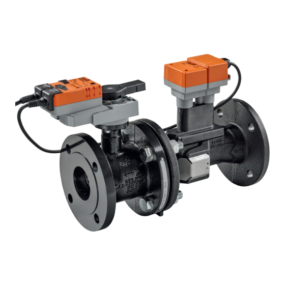
Characterised control valve with
sensor-operated flow control, 2-way,
Flange, PN 16 (EPIV)
• Nominal voltage AC/DC 24 V
• Control modulating, communicative
• For closed cold and warm water
systems
• For modulating control of air-
handling and heating systems on the
water side
• Communication via Belimo MP-Bus
or conventional control
• Conversion of active sensor signals
and switching contacts
Type overview
Technical data
Functional data
www.belimo.com
Technical data sheet
Type
EP065F+MP
EP080F+MP
EP100F+MP
EP125F+MP
EP150F+MP
kvs theor.: Theoretical kvs value for pressure drop calculation
Electrical data
Nominal voltage
Nominal voltage frequency
Nominal voltage range
Power consumption in operation
Power consumption in rest position
Power consumption for wire sizing
Connection supply / control
Parallel operation
Torque Motor
Operating range Y
Input Impedance
Operating range Y variable
Options positioning signal
Position feedback U
Position feedback U note
Position feedback U variable
Sound power level Motor
Adjustable flow rate V'max
Control accuracy
Media
Medium temperature
Close-off pressure ∆ps
Differential pressure ∆pmax
Flow characteristic
Leakage rate
Pipe connectors
Installation position
Servicing
Manual override
EP..F+MP • en-ap • 2019-06-03 • subject to changes
DN
DN
V'nom
V'nom
[ ]
["]
[ l/s]
[ l/min]
65
2 1/2
8
480
80
3
11
660
100
4
20
1200
125
5
31
1860
150
6
45
2700
AC/DC 24 V
50/60 Hz
AC 19.2...28.8 V / DC 21.6...28.8 V
9.5 W
6.5 W
13 VA
Cable 1 m, 4 x 0.75 mm²
Yes (note the performance data)
20 Nm (DN 65...80)
40 Nm (DN 100...150)
DC 2...10 V
100 kΩ
Start point DC 0.5...24 V
End point DC 8.5...32 V
Modulating (DC 0...32 V)
DC 2...10 V
Max. 1 mA
Start point DC 0.5...8 V
End point DC 2...10 V
45 dB(A)
30...100% of Vnom
±5% (of 25...100% Vnom) @ 20°C / Glycol 0%
vol.
Cold and warm water, water with glycol up to
max. 60% vol.
-10...120°C
690 kPa
340 kPa
equal percentage (VDI/VDE 2178), optimised in
the opening range (switchable to linear)
air-bubble tight, leakage rate A (EN 12266-1)
Flange PN 16 according to EN 1092-2
upright to horizontal (in relation to the stem)
maintenance-free
with push-button, can be locked
EP..F+MP
kvs theor.
PN
n(gl)
[ m³/h]
[ ]
[ ]
16
3.2
50
74
16
3.2
126
16
3.2
16
3.2
195
16
3.2
254
1
Advertisement
Table of Contents

Related Manuals for Belimo EP065F+MP


Summarization of Contents
Technical data
Electrical data
Details regarding nominal voltage, frequency, power consumption, and electrical connections for the valve.
Functional data
Covers torque, operating ranges, feedback signals, and control accuracy of the valve.
Flow measurement
Details on ultrasonic volumetric flow measurement principle and accuracy.
Safety
Covers protection class, EMC, operating mode, voltage, pollution degree, and ambient conditions.
Materials
Specifies materials used for the flow measuring pipe, closing element, stem seal, and ball seat.
Product features
Transmission behaviour HE
Describes heat exchanger transmission behavior, power Q vs. flow V, and equal-percentage characteristic curve.
Control characteristics
Explains velocity measurement, signal conversion, characteristic curves, and feedback for precise control.
Definition Flow control
Defines Vnom, Vmax, Vmin, and illustrates flow rate setting with characteristic curves.
Creep flow suppression
Explains electronic override for low flow speeds to maintain measurement accuracy.
Opening valve
Describes valve behavior when opening, activated by positioning signal Y up to 1% of V nom.
Closing valve
Details valve behavior when closing, maintaining flow at 1% of V nom until signal drops.
Converter for sensors
Explains connection options for sensors and MP-Bus transmission of signals.
Configurable actuators
Covers factory settings and parameter modification using Belimo Service Tools.
Positioning signal inversion
Explains inversion of positioning signal for analogue control, reversing standard behavior.
Hydraulic balancing
Describes on-site adjustment of maximum flow rate using Belimo tools or management system.
Manual override
Details manual override functionality via push-button, with gear engagement/disengagement.
High functional reliability
Highlights overload protection, no limit switches, and automatic stopping at end stop.
Accessories
Gateways
Lists available gateways for communication protocols like BACnet, Modbus, and LonWorks.
Electrical accessories
Details accessories such as stem heating flanges and connection cables for MP actuators.
Service Tools
Lists service tools like ZTH AP, PC-Tool, and level converters for actuator configuration.
Electrical installation
Wiring diagrams
Illustrates wiring diagrams for AC/DC 24 V modulating control and MP-Bus operation.
Functions
Functions when operated on MP-Bus
Details MP-Bus connection, network topology, and actuator/sensor connections.
Functions for actuators with specific parameters
Covers override control, limiting with relay contacts, and 3-point control modes.
Operating controls and indicators
Push-button and LED display green
Describes the green LED and push-button functions for power status and adaptation.
Push-button and LED display yellow
Explains the yellow LED and push-button for MP bus status and confirmation.
Gear disengagement button
Details the button for disengaging the gear, enabling manual override and stopping the motor.
Service plug
Describes the service plug for connecting parameterization and service tools.
Installation notes
Recommended installation positions
Specifies permitted installation positions for the ball valve, excluding hanging orientation.
Mounting position in the return
Recommends mounting the valve in the return line for optimal function.
Water quality requirements
Outlines water quality requirements, conductivity, and protection from debris for valve longevity.
Stem heating
Explains the purpose and usage of stem heating to prevent condensation and corrosion.
Servicing
States that valves, actuators, and sensors are maintenance-free; outlines service procedures.
General notes
Flow direction
Emphasizes compliance with flow direction arrow for accurate flow rate measurement.
Inlet section
Specifies the requirement for a flow-calming section (min. 5x DN) upstream for measuring accuracy.
Valve selection
Guides valve selection based on maximum required flow rate (Vmax) and heat exchanger diameter.
Minimum differential pressure
Explains calculation of minimum pressure drop (Apmin) required for desired volumetric flow (Vmax).
Behaviour of sensor failure
Describes the switch from flow control to position control upon sensor failure and recovery.
Service
Service Tools connection
Details parameterization via ZTH AP service socket and PC tool connection.
Dimensions / Weight
Dimensional drawings
Presents dimensional drawings and notes on hand crank demounting for various valve types.
Need help?
Do you have a question about the EP065F+MP and is the answer not in the manual?
Questions and answers