Table of Contents
Advertisement
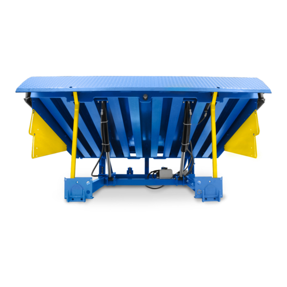
INSTALLATION & TECHNICAL MANUAL
ACTUAL PRODUCT MAY NOT APPEAR EXACTLY AS SHOWN
WARNING
Do not install, operate or service this product unless you
have read and fully understand the entire contents of this
manual in combination with owners manual. Failure to do
so may result in property damage, bodily injury or death.
STARTING FROM MAY 1, 2018 / SERIAL # 440190.1
PIT STYLE DOCK LEVELERS
ISSUE DATE: AUGUST 31, 2018 REV.1 (PART # 038-1073EI)
Advertisement
Table of Contents
Troubleshooting

Related Manuals for Blue Giant H6006


Summary of Contents for Blue Giant H6006
- Page 1 INSTALLATION & TECHNICAL MANUAL PIT STYLE DOCK LEVELERS ACTUAL PRODUCT MAY NOT APPEAR EXACTLY AS SHOWN WARNING Do not install, operate or service this product unless you have read and fully understand the entire contents of this manual in combination with owners manual. Failure to do so may result in property damage, bodily injury or death.
-
Page 2: Table Of Contents
BLUE GIANT SERIES DOCK LEVELERS—INSTALLATION & TECHNICAL MANUAL TABLE OF CONTENTS GENERAL SITE CHECKLIST FOR DOCK LEVELLER INTRODUCTION WARRANTY INFORMATION EXCLUSION OF LIABILITY MANUFACTURER’S NOTE INSTALLER’S GUIDELINES SAFETY MESSAGE COLOR IDENTIFICATION OPERATIONAL SAFETY WARNINGS LOCKOUT / TAGOUT PROCEDURE AND RULES... - Page 3 BLUE GIANT SERIES DOCK LEVELER—INSTALLATION & TECHNICAL MANUAL TABLE OF CONTENTS 24.0 ALTERNATIVE: BLUE GENIUS™ CONTROL PANEL INSTALLATION 25.0 BLUE GENIUS™ ELECTRICAL WIRING INSTALLATION 25.1 BLUE GENIUS™ CONTROL PANEL WIRING LAYOUT 26.0 BLUE GENIUS™ GOLD WIRING DIAGRAM—115V SINGLE PHASE 26.1 BLUE GENIUS™...
-
Page 4: General Site Checklist For Dock Leveller
BLUE GIANT SERIES DOCK LEVELERS—INSTALLATION & TECHNICAL MANUAL 1.0 GENERAL SITE CHECKLIST FOR DOCK LEVELER Comments Review site conditions. Have you completed and reviewed site survey report? Does the pit fit the leveler that has been provided? ... -
Page 5: Introduction
To validate warranty on recently purchased equipment, please complete and submit your information with our • The installation of Blue Giant dock products should comply with all applicable local or national building codes and regulations, online Warranty Registration at www.bluegiant.com. -
Page 6: Safety Message Color Identification
BLUE GIANT SERIES DOCK LEVELERS—INSTALLATION & TECHNICAL MANUAL 3.0 SAFETY MESSAGE COLOR IDENTIFICATION This manual includes color-coded safety messages that clarify instructions and specify areas where potential hazard exists. To prevent the possibility of equipment damage and serious injury or death, please observe strictly the instructions and warnings contained in the messages. -
Page 7: Lockout / Tagout Procedure And Rules
The machine or equipment power supply shall be locked in the OFF position or disconnected from the energy source. Blue Giant strongly recommends that only OSHA-approved lockout devices and procedures be utilized. The energy isolating device must bear a prominent warning tag indicating that work is being done on the equipment and the name of the authorized employee responsible for the lockout. -
Page 8: Dock Leveler Forklift Handling
Failure to follow proper handling procedures may result in serious equipment damage. All Blue Giant dock levelers come equipped with fork pockets located at the rear of the unit for safe and convenient handling. To ensure that the dock leveler does not experience any unnecessary damage, always lift from the rear fork pockets when using a forklift. -
Page 9: Dock Strut Set-Up
BLUE GIANT SERIES DOCK LEVELER—INSTALLATION & TECHNICAL MANUAL 7.0 DOCK STRUT SET-UP DANGER WARNING Failure to properly secure the dock leveler deck prior to Post safety warnings and barricade work area at dock and ground level. Notify all affected personnel that work is being working underneath it may result in property damage, bodily injury, or death. -
Page 10: Installation Layout
BLUE GIANT SERIES DOCK LEVELERS—INSTALLATION & TECHNICAL MANUAL 8.0 INSTALLATION LAYOUT SINGLE PUSH BUTTON NEW CONSTRUCTION CONTROL STATION (mounted on drivers side) (CONDUIT POURED IN CONCRETE) 20" (508mm) Run one 1/2" (16mm) trade size conduit 14" from the control station to the motor (356mm) junction box. -
Page 11: Tools Required For Installation
BLUE GIANT SERIES DOCK LEVELER—INSTALLATION & TECHNICAL MANUAL 9.0 TOOLS REQUIRED FOR INSTALLATION Hammer Drill Tape Measure Crowbar 3'-5' " and ¼" Concrete Bit Carbide 2' Level Chisel Large " x " Screwdriver Small Flat Screwdriver Chip Hammer Ball Peen Hammer (flat tip to be suitable for .150 slot) -
Page 12: Recommended Equipment For Rigging Or Hoisting
BLUE GIANT SERIES DOCK LEVELERS—INSTALLATION & TECHNICAL MANUAL 9.0 TOOLS REQUIRED FOR INSTALLATION CONT'D Funnel Angle Measurement Tool Drill/Screwdriver Nut Driver Drill Bit 5/16" Conduit Bender Torque Wrench 9.1 RECOMMENDED EQUIPMENT FOR RIGGING OR HOISTING Boom Truck Forklift Sling and Hoist Ring... -
Page 13: Installation For Pit Type Dock Levelers
10.1 GENERAL DESCRIPTION See below for names of general Blue Giant dock components. These names will be used throughout the manual. Temporary... -
Page 14: General Description - Hydraulic Dock Leveler
BLUE GIANT SERIES DOCK LEVELERS—INSTALLATION & TECHNICAL MANUAL 10.2 GENERAL DESCRIPTION - HYDRAULIC DOCK LEVELER See below for names of assemblies unique to the Hydraulic Dock Leveler. These names will be used throughout the manual. LEGEND Lifting Assembly Lip Deployment Assembly Hydraulic Powerpack 10.3 GENERAL DESCRIPTION -... -
Page 15: Equipment Component Illustrations
BLUE GIANT SERIES DOCK LEVELER—INSTALLATION & TECHNICAL MANUAL 11.0 EQUIPMENT COMPONENT ILLUSTRATIONS 11.1 COMPONENTS AS SHIPPED CHECKLIST OPERATING INSTRUCTIONS Only for the Airbag Dock Leveler Supported by a minimum of six heavy-duty U-beams, the Airbag Dock Leveler has a high-volume, low-pressure air lifting system that presents an eco-friendly alternative to oil-powered hydraulics. -
Page 16: General Dimensions
BLUE GIANT SERIES DOCK LEVELERS—INSTALLATION & TECHNICAL MANUAL 12.0 GENERAL DIMENSIONS 4.5" Dimensions "E" includes deck plate, lip plate, and .25" gap. * 3" taper dimension on both sides of lip (7' levelers only). LIP LENGTH (D) MODEL TOTAL DECK WIDTH (A) FRAME WIDTH (B) 16"... -
Page 17: Pit Dimensions
BLUE GIANT SERIES DOCK LEVELER—INSTALLATION & TECHNICAL MANUAL 13.0 PIT DIMENSIONS PIT WIDTH (W) PIT LENGTH (L) NOMINAL SIZE 6' x 6' 1829 x 1829mm 1600 6' x 8' 1829 x 2438mm 2210 1880 6' x 10' 1829 x 3048mm... - Page 18 BLUE GIANT SERIES DOCK LEVELERS—INSTALLATION & TECHNICAL MANUAL 14.1 DOCK LEVELER INSTALLATION STEP 1 Measure the height of the dock leveler rear corners from the bottom of frame to top of dock deck, typically 19" (483 mm). Measure depth of pit at both rear corners where rear bottom corners of frame will be positioned.
-
Page 19: Dock Leveler Installation
BLUE GIANT SERIES DOCK LEVELER—INSTALLATION & TECHNICAL MANUAL 14.1 DOCK LEVELER INSTALLATION CONT'D. Chain Lift STEP 4 Sling the dock leveler into place squarely above the pit and lower gently. Locate and square the dock leveler to best suit both the pit and dock face. - Page 20 BLUE GIANT SERIES DOCK LEVELERS—INSTALLATION & TECHNICAL MANUAL 14.1 DOCK LEVELER INSTALLATION CONT'D. STEP 7 Rear curb angle Rear Frame 6" Finish weld here Finish welding the rear frame to the rear curb angle of the pit. Width WELD HERE of weld is dependent on dock width.
- Page 21 BLUE GIANT SERIES DOCK LEVELER—INSTALLATION & TECHNICAL MANUAL 14.1 DOCK LEVELER INSTALLATION CONT'D. Frame shorter than pit Mounting Foot STEP 10 Ensure that the mounting feet are flush to the front of embedded curb angle. Curb Angle NOTE: Tack weld on each shim per side per lip keeper.
- Page 22 BLUE GIANT SERIES DOCK LEVELERS—INSTALLATION & TECHNICAL MANUAL 14.1 DOCK LEVELER INSTALLATION CONT'D. STEP 13 Refer to next step for all lip keeper mounting options and instructions. If necessary, align the lip keepers by moving them up or down until 3/8"...
- Page 23 BLUE GIANT SERIES DOCK LEVELER—INSTALLATION & TECHNICAL MANUAL 14.1 DOCK LEVELER INSTALLATION CONT'D. STEP 14 Remove the shipping bolts. Remove the Shipping Hoist DANGER If installing a Mechanical dock leveler, be aware that the deployment mechanism may have triggered during shipping and, as a result, the dock may pop up when the shipping bolts are removed.
- Page 24 BLUE GIANT SERIES DOCK LEVELERS—INSTALLATION & TECHNICAL MANUAL 14.1 DOCK LEVELER INSTALLATION CONT'D. STEP 17 With the dock leveler raised and secured with dock strut and safety 16" lip stand. Finish weld the lip keepers at least 4" total weld (3/16" - 1/4").
- Page 25 BLUE GIANT SERIES DOCK LEVELER—INSTALLATION & TECHNICAL MANUAL 14.1 DOCK LEVELER INSTALLATION OPTIONAL STEP 20 To lower the leveling legs: Remove the shipping pin and leveling legs will drop. Use a (insert dim) socket to turn the bolt. As the bolt turns, the leveling legs will press to the pit floor.
- Page 26 BLUE GIANT SERIES DOCK LEVELERS—INSTALLATION & TECHNICAL MANUAL 14.1 DOCK LEVELER INSTALLATION CONT'D. STEP 22 86" (2184mm) Laminated Install specified dock bumpers as required. bumper (2x) Ensure a maximum distance of 86" (2184mm) between the inner edges of the bumper. If a vertical curb angle exists, mount there.
-
Page 27: Sp1 Control Station Installation
BLUE GIANT SERIES DOCK LEVELER—INSTALLATION & TECHNICAL MANUAL 14.1 DOCK LEVELER INSTALLATION CONT'D. OPERATING INSTRUCTIONS Only for the Airbag Dock Leveler Supported by a minimum of six heavy-duty U-beams, the Airbag Dock Leveler has a high-volume, low-pressure air lifting system that presents an eco-friendly alternative to oil-powered hydraulics. -
Page 28: Sp1 Wiring Diagram-110-130V Single Phase
BLUE GIANT SERIES DOCK LEVELERS—INSTALLATION & TECHNICAL MANUAL 16.1 SP1 WIRING DIAGRAM—110–130V SINGLE PHASE 28 AUGUST 31, 2018 REV.1 (PART # 038-1073EI) -
Page 29: Sp1 Wiring Diagram-208-240V Single Phase
BLUE GIANT SERIES DOCK LEVELER—INSTALLATION & TECHNICAL MANUAL 16.2 SP1 WIRING DIAGRAM—208–240V SINGLE PHASE AUGUST 31, 2018 REV.1 (PART # 038-1073EI) -
Page 30: Laminated Bumper Installation
BLUE GIANT SERIES DOCK LEVELERS—INSTALLATION & TECHNICAL MANUAL 17.0 LAMINATED BUMPER INSTALLATION 17.1 WEDGE ANCHORS Quantity Description Part # 1. Mark and position each hole on the dock face. 6" x " 010-108 2. Drill each hole in the concrete using a 5/8" (16mm) or carbide- tipped masonry drill bit. -
Page 31: Planned Maintenance
Before doing any electrical work, make certain the power is disconnected and properly tagged or locked off. When conducting maintenance, use only Blue Giant approved lubricants. Improper lubrication or adjustments may cause operational problems. See the Owner's Manual supplied for detailed Planned Maintenance checklist. -
Page 32: Mechanical Dock Leveler Troubleshooting
BLUE GIANT SERIES DOCK LEVELERS—INSTALLATION & TECHNICAL MANUAL PROBLEM PROBLEM CAUSE The fall-safe velocity fuse located at the bottom of the deck cylinder is in the locked- closed position. Deck will not lower. • Deck lowering speed is set too fast. Turn lowering speed adjustment NEEDLE VALVE clockwise in 1/8 turn increments until travel time is 7 seconds maximum from fully raised to level/home position. - Page 33 BLUE GIANT SERIES DOCK LEVELER—INSTALLATION & TECHNICAL MANUAL PROBLEM PROBLEM CAUSE The lip lock is not engaging. The dock spring may be broken or stretched, or the lock itself The lip does not lock after may have seized. fully extending.
-
Page 34: Alternative: Sp2 Control Station Installation
BLUE GIANT SERIES DOCK LEVELERS—INSTALLATION & TECHNICAL MANUAL 22.0 ALTERNATIVE: SP2 CONTROL STATION INSTALLATION NOTICE The use of ESD protocol is now needed when handling any controls mentioned hereafter. Remove the SP2 control station from its box and install the wall-mounting tabs on the back of the control station. The mounting brackets must be installed to suit site / wall conditions. -
Page 35: Sp2 Wiring Diagram-115V Single Phase
BLUE GIANT SERIES DOCK LEVELER—INSTALLATION & TECHNICAL MANUAL 23.0 SP2 WIRING DIAGRAM—115V SINGLE PHASE AUGUST 31, 2018 REV.1 (PART # 038-1073EI) -
Page 36: Alternative: Blue Genius™ Control Panel Installation
BLUE GIANT SERIES DOCK LEVELERS—INSTALLATION & TECHNICAL MANUAL 24.0 ALTERNATIVE: BLUE GENIUS™ CONTROL PANEL INSTALLATION Anchor point (hardware not provided) Wall mounting tab Wall mounting tab Blue Genius™ control panel—mounting on wall (typical decal shown). Blue Genius™ control panel—wall-mounting brackets. -
Page 37: Blue Genius™ Electrical Wiring Installation
BLUE GIANT SERIES DOCK LEVELER—INSTALLATION & TECHNICAL MANUAL 25.0 BLUE GENIUS™ ELECTRICAL WIRING INSTALLATION NOTICE All wiring must comply with local and national electrical building codes. General notes to electrician / installer: 1. Run communication wire in separate raceways back to the Blue Genius™... -
Page 38: Blue Genius™ Control Panel Wiring Layout
BLUE GIANT SERIES DOCK LEVELERS—INSTALLATION & TECHNICAL MANUAL 25.1 BLUE GENIUS™ CONTROL PANEL WIRING LAYOUT 115V SINGLE PHASE 230V SINGLE PHASE MOTOR MOTOR POWER POWER J-BOX J-BOX EXTERIOR REMOTE EXTERIOR REMOTE TRAFFIC TRAFFIC LIGHTS LIGHTS COMM CABLE COMM CABLE OPTIONAL... -
Page 39: Blue Genius™ Gold Wiring Diagram-115V Single Phase
BLUE GIANT SERIES DOCK LEVELER—INSTALLATION & TECHNICAL MANUAL 26.0 BLUE GENIUS™ GOLD WIRING DIAGRAM—115V SINGLE PHASE AUGUST 31, 2018 REV.1 (PART # 038-1073EI) -
Page 40: Blue Genius™ Gold Wiring Diagram-230V Single Phase
BLUE GIANT SERIES DOCK LEVELERS—INSTALLATION & TECHNICAL MANUAL 26.1 BLUE GENIUS™ GOLD WIRING DIAGRAM—230V SINGLE PHASE 40 AUGUST 31, 2018 REV.1 (PART # 038-1073EI) -
Page 41: Optional Exterior Driver Traffic Light Installation
BLUE GIANT SERIES DOCK LEVELER—INSTALLATION & TECHNICAL MANUAL 27.0 OPTIONAL EXTERIOR DRIVER TRAFFIC LIGHT 27.1 OPTIONAL EXTERIOR DRIVER WARNING SIGN INSTALLATION INSTALLATION Mount the exterior traffic light approximately 84" - 96" (2134 mm When installing the driver warning sign below the exterior traffic - 2438 mm) above the driveway surface. -
Page 42: Optional Lip Home Sensor Package Installation - Blue Genius™ Equipped Docks Only
BLUE GIANT SERIES DOCK LEVELERS—INSTALLATION & TECHNICAL MANUAL 28.0 OPTIONAL LIP HOME SENSOR PACKAGE INSTALLATION - BLUE GENIUS™ EQUIPPED DOCKS ONLY STEP 1 Remove the front holding nut from the proximity sensor and insert the sensor into one of the two larger holes in the mounting foot of the dock leveler. - Page 43 BLUE GIANT SERIES DOCK LEVELER—INSTALLATION & TECHNICAL MANUAL NOTES AUGUST 31, 2018 REV.1 (PART # 038-1073EI)
- Page 44 Corporate 410 Admiral Blvd USA 6350 Burnt Poplar Road Mississauga, ON, Canada L5T 2N6 Greensboro, NC 27409 t 905.457.3900 f 905.457.2313 www.bluegiant.com If calling within North America: t 1.800.872.2583 f 1.888.378.5781 © Copyright Blue Giant Equipment Corporation 2017...
Need help?
Do you have a question about the H6006 and is the answer not in the manual?
Questions and answers