Table of Contents
Advertisement
Quick Links
OWNER'S MANUAL
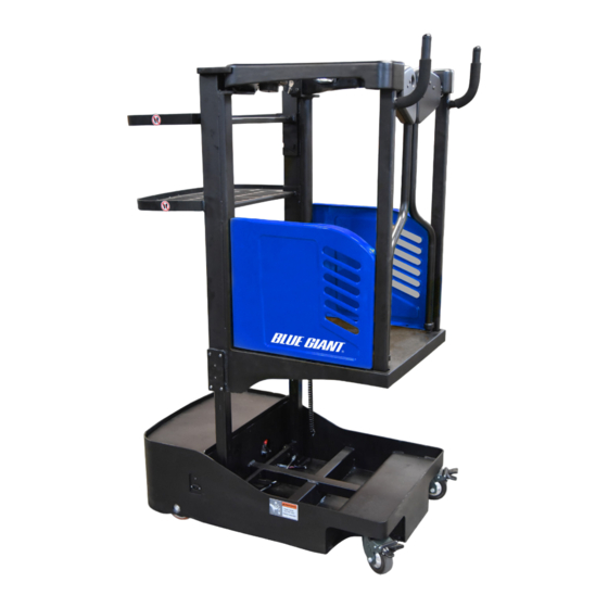
BG E-STEP SEMI ELECTRIC ACCESS VEHICLE
ACTUAL PRODUCT MAY NOT APPEAR EXACTLY AS SHOWN
WARNING
Do not operate or service this product unless you have
read and fully understand the entire contents of this
manual. Failure to do so may result in property damage,
bodily injury or death.
ISSUE DATE: DECEMBER 7, 2020 REV. 1.0 (PART # 038-XXXXE)
Advertisement
Table of Contents

Subscribe to Our Youtube Channel
Related Manuals for Blue Giant BG E-Step


Summary of Contents for Blue Giant BG E-Step
- Page 1 OWNER’S MANUAL BG E-STEP SEMI ELECTRIC ACCESS VEHICLE ACTUAL PRODUCT MAY NOT APPEAR EXACTLY AS SHOWN WARNING Do not operate or service this product unless you have read and fully understand the entire contents of this manual. Failure to do so may result in property damage, bodily injury or death.
- Page 2 WARNING Do not operate this vehicle unless you have been Before elevating platform be sure access gates are in authorized and trained to do so, and have read all position. Keep feet on platform floor at all times while warnings and instructions in Operator’s Manual and on using vehicle, never climb onto access gates or this vehicle.
- Page 3 NOTES...
-
Page 4: Table Of Contents
TABLE OF CONTENTS Section Page Section Page 1 DESCRIPTION ............1-1 GENERAL DESCRIPTION ......1-1 6 LOAD WHEEL, CASTERS ......... 6-1 DATA PLATE AND WARNING DECAL ..1-3 LOAD WHEEL..........6-1 INSTALLATION / WARRANTY 6-1.1 Removal........... 6-1 CHECK LIST..........1-3 6-1.2 Installation..........6-1 CASTER............6-1 2 PLANNED MAINTENANCE ........2-1 GENERAL.............2-1 7 HYDRAULIC SYSTEM SERVICING...... -
Page 5: Description
SECTION 1 DESCRIPTION 1-1. INTRODUCTION. 1-2. GENERAL DESCRIPTION. This publication describes the 24 volt BG E-Step The self-propelled BG E-Step Semi-Electric Access Semi-Electric Access Vehicle by Blue Giant. Included Vehicle Electric Access Vehicle lifts and transports up are planned maintenance instructions, lubrication to 750 pounds capacity including load and operator. - Page 6 R8552 Figure 1-2 ITEM CONTROL / DISPLAY FUNCTION Cup holder Storage Battery discharge indicator Display battery power level. Horn Button Activates the horn. Lift Button Lift the operator platform. Lowering Button Lower the operator platform. Switches control current on and off. Removing the Key switch key prevents the access vehicle from being switched on by unauthorized personnel.
-
Page 7: Data Plate And Warning Decal
Blue Giant initiate t t all e en Blue Giant 1-3. DATA PLATE AND WARNING DECAL. Blue Giant Authorized Dealer for replacement. BG E-STEP MODEL SERIAL 2281300008 NUMBER WEIGHT LB/KG 630/285 BLUE GIANT EQUIPMENT CORPORATION www.BlueGiant.com R8553 Figure 1-3 Data Plate... - Page 8 RGA# A confirmation receipt will be faxed back with a warranty claim number attached. If Blue Giant deems that part(s) need to be returned, an RGA numbered form will be faxed as well. Please include a copy of the RGA form with returning part(s) to Blue Giant Brampton location only.
-
Page 9: Planned Maintenance
The owner and user are required by ANSI A92.6 to when eyes are affected. A baking soda ensure frequent inspections of the BG E-Step Semi- solution (one pound to one gallon of Electric Access Vehicle occur and are performed in water) applied to spilled acid until accor-dance with the following points: 1. -
Page 10: 2-5.2 Safety Rules
2-5.2. Safety Rules CAUTION: Never smoke or bring open flame near the battery. Gas formed during • Wear protective clothing, such as rubber apron, charging is highly explosive and can gloves, boots and goggles when performing any cause serious injury. maintenance on batteries. -
Page 11: Replacing Batteries
Carefully lift the batteries out of the vehicle. for installation please reverse step 1-5. Replace only with original OEM batteries or batteries approved by an authorized Blue Giant dealer. Contact your authorized Blue Giant dealer for information on optional batteries and battery... -
Page 12: Lubrication
R8556 Figure 2-2 Lubrication Diagram 2-8. LUBRICATION. Table 2-2 Recommended Lubricants Code Description Used for Refer to Table 2-2 for the recommended types of grease and oil in conjunction with Figure 2-2 identifies L-HM46 Hydraulic oil the items requiring lubrication. Polylub GA352P Multi-purpose grease... -
Page 13: Troubleshooting
SECTION 3 TROUBLESHOOTING 3-1. GENERAL Does Not Operate Forward or Reverse: Trouble With Braking: Trouble With Lifting Or Lowering, and Table 3-1 as a guide to determine possible causes Miscellaneous malfunctions. of trouble. The table is divided into five main categories: Vehicle and Hydraulic System Will Not Operate: Vehicle Table 3-1 Troubleshooting Chart Table 3-1 Troubleshooting Chart - Continued... - Page 14 NOTES...
-
Page 15: Compartment Cover Removal
SECTION 4 COMPARTMENT COVER REMOVAL 4-1. FRONT COMPARTMENT COVER 4-1.2. Cover Installation. Carefully position cover on the vehicle. 4-1.1. Cover Removal. Install four screws. Engage the emergency power disconnect switch Disengage the emergency power disconnect and turn off key switch. switch and turn on key switch. - Page 16 NOTES...
-
Page 17: Floor Lock System
SECTION 5 FLOOR LOCK SYSTEM 5-1. FLOOR LOCK. Disconnect electric motor from harness. Remove the mounting screws and motor The floor lock system consists of a motor mounted assembly. horizontally that moves 2 stability pads to touch the floor when the platform is raised up. The lock is Place the new motor assembly into position and electrically applied &... - Page 18 NOTES...
-
Page 19: Load Wheel, Casters
SECTION 6 LOAD WHEEL, CASTERS 6-1. LOAD WHEEL. Reassemble bearings in load wheel. Position load wheel on the axle and install two 6-1.1. Removal bolts, two lock washers and two flat washers. Engage the emergency power disconnect switch Install cover and secure with the screws. and turn off key switch. - Page 20 ED_0001 Figure 6-1 Frame...
-
Page 21: Hydraulic System Servicing
SECTION 7 HYDRAULIC SYSTEM SERVICING 7-1. LINES AND FITTINGS 7-2. HYDRAULIC PUMP, MOTOR, AND RESER- VOIR ASSY WARNING: When the platform is raised, pressure hydraulic pump/motor assembly exists in the hydraulic system lines and disassembled and repaired. However, a defective fittings. - Page 22 ED_0004 Figure 7-1 Hydraulic System...
-
Page 23: 7-2.2 Installation
7-2.2. Installation WARNING: Support lift cylinder before performing the following steps to prevent cylinder Install pump/motor assembly as described in from falling. paragraph 7-2.1. Remove the five screws and lock washers that Reconnect hose to pump/motor assembly. holds down the cylinder mount plate at the top of Connect electrical leads to motor and solenoid of the mast. - Page 24 NOTES...
-
Page 25: Electrical Components
SECTION 8 ELECTRICAL COMPONENTS 8-1. ELECTRICAL CONTROL PANEL 8-2. HORN REPLACEMENT. Engage the emergency power disconnect switch 8-1.1. Maintenance and turn off key switch. NOTE: Erratic operation of the vehicle may be Remove the compartment cover as described in caused by a defective electrical component. paragraph 4-1.1. -
Page 26: Battery Replacement
8-3. BATTERY REPLACEMENT. Remove the Control Panel Assembly out of the way. Replace the battery as described in paragraph 2-7. Disconnect cables and harnesses from charger. Remove the charger mounting screws and charger. 8-4. BATTERY CHARGER. 8-4.2. Installation. 8-4.1. Removal. Position the new charger in frame and secure with Engage the emergency power disconnect switch four screws. -
Page 27: Platform Cable Replacement
8-5. PLATFORM CABLE REPLACEMENT. Disconnect the electrical connectors at each end of the mast cable. 8-5.1. Platform Disconnect the mounting clamps and remove wire With the lift vehicle wheels securely blocked, raise ties. the Platform approximately two feet and position Lift harness with protective chain from sheave. - Page 28 NOTES...
-
Page 29: Optional Equipment
SECTION 9 OPTIONAL EQUIPMENT 9-1. N/A... - Page 30 NOTES...
-
Page 31: Illustrated Parts Breakdown
SECTION 10 ILLUSTRATED PARTS BREAKDOWN Following is an illustrated parts breakdown of assemblies and parts associated with the BG E-Step Semi-Electric Access Vehicle. - Page 32 ED_0001 Figure 10-1 Frame...
- Page 33 Frame QTY. POS. PART NUMBER DESCRIPTION NOTES REQD. 1650-101000-00 FRAME 1650-100001-00 SLIDER 0000-000119-00 SCREW M5×12 0000-000550-00 NUT M8 0000-000712-00 SCREW M8×20 1650-100100-00 CASTER ASSEMBLY 1650-100003-00 PLATE 1650-100200-00 MACHINE LEG 1650-102100-00 BRAKE GUIDE POST 1650-100300-00 BEARING 0000-001368-00 CIRCLIP Ø28 1650-102200-00 BRAKE BRACKET 3090-000000-04 DEEP GROOVE BALL BEARING 6204 1650-100007-00...
- Page 34 ED_0002 Figure 10-2 Operator Platform...
- Page 35 Operator Platform QTY. POS. PART NUMBER DESCRIPTION NOTES REQD. 1650-701000-00 LOADING FRAME 2028-019000-04 SLEEVE 1612 1600-704000-0B LEFT DOOR 1600-704002-0B BACK COVER 0000-000119-00 SCREW M5×12 1600-704001-0B DOOR HANDLE 2028-007000-03 SCREW M6X12 1650-700009-00 HANDLEBAR GRIP 1600-700003-00 SPRING LEFT 2028-019000-44 SLEEVE 1618F 0000-000028-00 SCREW M4×12 1600-700010-00 SPRING RIGHT...
- Page 36 ED_0003 Figure 10-3 Operating Control Assembly...
- Page 37 Operating Control Assembly QTY. POS. PART NUMBER DESCRIPTION NOTES REQD. 1650-700005-00 LEFT ARMREST 0000-001410-00 SCREW M12×30 1600-300100-00 RIGHT ARMREST 3020-020000-23 SCREW M5×16 1650-700004-00 RIGHT BOTTOM COVER 1650-700003-00 LEFT BOTTOM COVER 1600-300004-00 RUBBER 1650-520007-10 WIRE HARNESS CK11-520012-00 BUTTON SWITCH 2291200219 CK11-520012-0A BUTTON SWITCH 2291200220 1115-510006-60...
- Page 38 EC_0009 Figure 10-4 Decals...
- Page 39 “NO STEP” WARNING LABEL 5080-000016-77 LOAD TRAYS LABEL 5080-000016-78 INDOOR/LEVEL SURFACE ONLY LABEL DECAL 5080-000016-79 PINCH POINT WARNING LABEL 5080-000016-15 Blue Giant DECAL 2069-000000-22 KEY SWITCH DECAL LABEL 2069-013000-06 POWER SHUT OFF LABEL 2069-000001-00 CONTROL BUTTON DECAL LABEL 5080-000016-81 DATA PLATE...
- Page 40 ED_0004 Figure 10-5 Hydraulic System...
- Page 41 Hydraulic System QTY. POS. PART NUMBER DESCRIPTION NOTES REQD. 1650-421000-00 HYDRAULIC 1650-411000-00 LIFT CYLINDER 1650-431000-00 LEFT OIL PIPE TUBE ASSEMBLY 1650-432000-00 RIGHT OIL PIPE TUBE ASSEMBLY 2701-121400-10 THROUGH JOINT 2707-141400-30 ARTICULATED JOINT 0000-000044-00 SEALING GASKET Ø14 0000-001674-00 SEALING GASKET Ø12 1650-100400-00 LINEAR ACTUATOR 3070-000000-16...
- Page 42 ED_0005 Figure 10-6 Hydraulic Pump Assembly...
- Page 43 Hydraulic Pump Assembly QTY. POS. PART NUMBER DESCRIPTION NOTES REQD. 1115-561001-0A BRUSH 1115-560001-00 HOSE CLAMPS D80 1118-420002-00 WIRE HARNESS 1115-560002-00 RELAY 24V/150A 1115-560003-00 DC MOTOR 0.8KW/24V 1115-560026-00 SCREW 1115-560025-00 O-RING 16.36×2.21 1115-560016-00 CHECK VALVE 1115-560017-00 SOLENOID VALVE 24V 1650-42010X-00 VALVE PLATE 1115-560005-00 THROTTLE 1650-42012X-00...
- Page 44 ED_0006 Figure 10-7 Lift Cylinder...
- Page 45 Lift Cylinder QTY. POS. PART NUMBER DESCRIPTION NOTES REQD. 1650-411000-00 LIFT CYLINDER ASSEMBLY 1650-QJYG-0A SEAL KIT Includes pos. 1 - 5 1650-41001X-00 DUST SEAL 1650-41002X-00 SEALING RING 20×28×5 1650-41003X-00 O-RINGS 32×2.4 2130-414000-00 RETAINER RING 1650-41004X-00 SUPPORT RING 10×4...
- Page 46 ED_0007 Figure 10-8 Electrical System...
- Page 47 Electrical System QTY. POS. PART NUMBER DESCRIPTION NOTES REQD. 1600-520014-00 CHARGER SWITCHING LINE 1115-520013-00 1650-500100-00 LITHIUM BATTERY (24V26AH) 0000-000723-00 SCREW M3×10 1115-500006-00 CHARGER CABLE USA 1120-540001-00 STAND 0000-000126-00 SCREW M6×16 0000-000550-00 NUT M8 0000-000210-00 FLAT PAD Ø8 1115-510003-00 FUSE 100A 1650-520008-10 CHARGER (24V/20A)...
- Page 48 ED_0008 Figure 10-9 Wiring Harness...
- Page 49 Wire Harness QTY. POS. PART NUMBER DESCRIPTION NOTES REQD. 1650-520001-10 MAIN WIRING HARNESS 1650-520009-10 WIRE HARNESS 1650-520002-10 WIRE HARNESS 1650-520003-10 WIRE HARNESS 1650-520004-10 RELAY WIRING HARNESS...
- Page 50 Corporate 410 Admiral Blvd USA 6350 Burnt Poplar Rd Mississauga ON L5T 2N6 Greensboro, NC 27409 t 905.457.3900 f 905.457.2313 www.bluegiant.com If calling within North America: t 1.800.872.2583 f 1.888.378.5781 © Copyright Blue Giant Equipment Corporation 2020...
Need help?
Do you have a question about the BG E-Step and is the answer not in the manual?
Questions and answers