Table of Contents
Advertisement
Installation Instructions
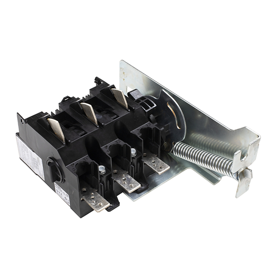
Universal Disconnect Switch Installation Instructions (200A)
(Cat 1494U-D200; Series A)
WARNING: To prevent electrical shock, disconnect from power source before installing or servicing. Follow NFPA 70E requirements. Install in suitable enclosure. Keep free from
contaminants.
Installation, adjustments, putting into service, use, assembly, disassembly, and maintenance shall be carried out by suitably trained personnel in accordance with applicable code of
practice. In case of malfunction or damage, no attempts at repair should be made. The product should be returned to the manufacturer for repair. Do not dismantle the product.
WARNING: The following procedures are critical to the proper operation of the disconnect handle and switch. Failure to follow these steps can result in damage to the equipment and/or
serious injury or death to the operator.
Tools Needed: 5/16", 3/8" & 7/16" Nut Drivers, Hammer, Center Punch, File, Flat Screwdriver, Phillips Screwdriver, 7/32" Drill Bit, Needlenose Pliers, Hacksaw
Table of Contents
Rod and Cable Operated Disconnect Switch Location........................................................................................................................................................ 2
Rod Operated Switch Installation.................................................................................................................................................................................................2
Handle Installation.........................................................................................................................................................................................................................2
Cutting Connecting Rod..............................................................................................................................................................................................................3
Connecting Rod Installation.......................................................................................................................................................................................................3
Cable Operated Switch Installation.............................................................................................................................................................................................4
Handle and Cable Mechanism Installation...........................................................................................................................................................................4
Cable to Switch Mechanism Installation................................................................................................................................................................................4
Rod Operated Adjustment Procedure........................................................................................................................................................................................5
Cable Operated Adjustment Procedure.....................................................................................................................................................................................5
Enclosure without Handle Cutout................................................................................................................................................................................................6
Door Catch Bracket Installation.....................................................................................................................................................................................................6
Trailer Fuse Block Installation.........................................................................................................................................................................................................7
Fuse Clip and Fuse Installation..................................................................................................................................................................................................8
Auxiliary Contact Installation.........................................................................................................................................................................................................9
Auxiliary Contact Wire Routing.....................................................................................................................................................................................................9
Line Terminal Adapter Installation...............................................................................................................................................................................................9
Electrical Interlock Installation.......................................................................................................................................................................................................9
Protective Cover Installation........................................................................................................................................................................................................10
Bulletin 1494U Disconnect Switch Component Accessory List......................................................................................................................................11
Page
Advertisement
Table of Contents

Related Manuals for Allen-Bradley 1494U-D200


Summarization of Contents
rod-and-cable-operated-disconnect-switch-location
disconnect-switch-location-and-installation
Locating the disconnect switch and installing the handle mechanism on the enclosure.
rod-operated-switch-installation
1494u-handle-installation-rod
Installing the handle, spring bracket, and defeater lever for rod operation.
cutting-connecting-rod
Measuring, marking, and cutting the connecting rod to the correct length.
connecting-rod-installation
Attaching the connecting rod to the switch and handle mechanisms for proper operation.
cable-operated-switch-installation
1494u-handle-cable-mechanism-installation
Installing the handle and cable mechanism for enclosures with a right flange.
cable-to-switch-mechanism-installation
Connecting the cable to the switch mechanism, ensuring proper routing and bend radius.
rod-operated-adjustment-procedure
rod-adjustment-procedure-if-switch-does-not-turn-on
Steps to adjust the rod mechanism when the switch cannot be turned ON.
rod-adjustment-procedure-if-switch-does-not-turn-off
Steps to adjust the rod mechanism when the switch cannot be turned OFF.
cable-operated-adjustment-procedure
adjusting-cable-extension-for-full-close
Procedure to adjust the cable length to ensure the switch fully closes.
adjusting-cable-retraction-for-full-open
Procedure to adjust the cable length to ensure the switch fully opens.
enclosure-modifications-for-handle-installation
locating-and-drilling-handle-holes
Procedures for locating and drilling holes for handle installation on enclosures without a cutout.
door-catch-bracket-installation
door-catch-bracket-mounting
Installing the door catch bracket, including considerations for different kits and enclosure types.
trailer-fuse-block-and-phase-barrier-installation
trailer-fuse-block-placement-and-phase-barrier-trimming
Positioning the fuse block and trimming phase barriers according to specifications.
lug-connectors-specifications
lug-connector-kits-and-torque-values
Details on lug connector kits, their material, wire range, and torque specifications.
fuse-clip-and-fuse-installation
direct-mount-fuse-clip-installation
Installing fuse clips directly for J-type fuses, including torque specifications.
fuse-installation-procedure
Installing fuses into the fuse clips, with required torque values.
accessory-installation-procedures
auxiliary-contact-installation-and-wiring
Installing auxiliary contacts and routing their associated wiring.
line-terminal-adapter-installation
Installing line terminal adapters, including wire clamp usage and ranges.
electrical-interlock-installation
Installing electrical interlocks and specifying required wire torque.
protective-cover-installation
installing-the-protective-cover
Step-by-step guide to fitting and securing the protective cover onto the switch assembly.
Need help?
Do you have a question about the 1494U-D200 and is the answer not in the manual?
Questions and answers