Table of Contents
Advertisement
Installation Instructions
Original Instructions
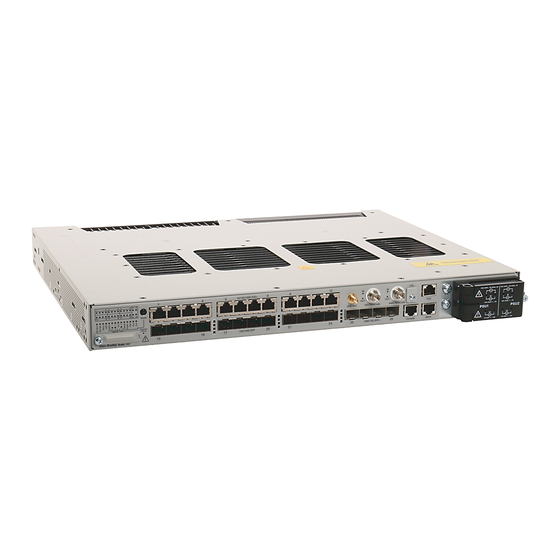
Stratix 5410 Ethernet Managed Switches and Power Supply
Catalog Numbers 1783-IMS28NDC, 1783-IMS28RDC, 1783-IMS28GNDC, 1783-IMS28GRDC, 1783-IMS28NAC,
1783-IMS28RAC,1783-IMS28GNAC, 1783-IMS28GRAC
Topic
Page
5
6
6
7
8
10
11
13
14
14
14
15
16
17
18
18
19
19
Advertisement
Table of Contents


Need help?
Do you have a question about the 1783-IMS28NDC and is the answer not in the manual?
Questions and answers