Table of Contents
Advertisement
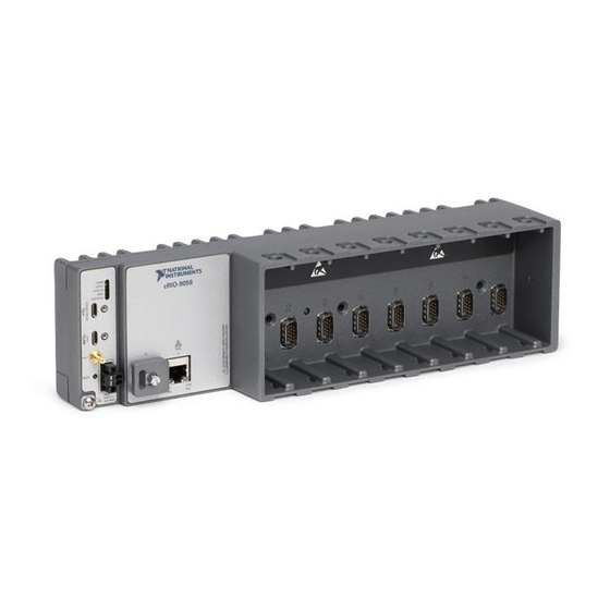
USER MANUAL
NI cRIO-905x
Embedded CompactRIO Controller with Real-Time Processor and
Reconfigurable FPGA
This document describes the features of the cRIO-905x and contains information about
mounting and operating the device.
In this document, the NI cRIO-9053, NI cRIO-9054, NI cRIO-9056, NI cRIO-9057 are
referred to collectively as cRIO-905x.
Advertisement
Table of Contents

Related Manuals for National Instruments NI cRIO-9056


Summarization of Contents
Connecting via Ethernet to Host or Network
Finding the cRIO-905x on Network (DHCP)
Locate the device on the network using DHCP and network settings.
Configuring cRIO-905x Startup Options
Configure the startup behavior of the cRIO-905x using MAX.
CRIO-905x Key Features Overview
Ports and Connectors Description
Description of the physical ports and connectors on the cRIO-905x.
USB 3.1 Host Port and PFI 0
Details on the USB 3.1 Type-C host port and the PFI 0 terminal.
Power Connector and Accessories
Information about the power connector and compatible accessories.
Power Supplies and MicroSD Storage
List of compatible NI power supplies and microSD card storage.
MicroSD Card Slot Cover and Ethernet Port
Using the microSD card slot cover and details on the Ethernet port.
CRIO-905x Buttons and Reset Functions
RESET Button Functionality
Functionality and behavior of the RESET button for system resets.
Troubleshooting Network Connectivity with RESET
Using the RESET button to troubleshoot network connectivity issues.
CRIO-905x Front Panel LEDs
POWER LED Indicator States
Explanation of the POWER LED states and their meanings.
STATUS LED Indicator States
Explanation of the STATUS LED states and error indications.
User LEDs for Application Status
Information about the USER1 and USER FPGA1 LEDs for custom status.
SD IN USE and Ethernet LED Indicators
Explanation of the SD IN USE and Ethernet LED states.
CRIO-905x Clock Routing Overview
80 MHz Timebase Details
Information about the 80 MHz Timebase used for timing signals.
Other Timebases and Onboard Clock
Details on 20/100 MHz Timebases, 40 MHz Onboard Clock, and other clocks.
Network Synchronization Across Devices
Internal Timebase Synchronization
Synchronization of the internal timebase with network devices.
Network-Based Synchronization Methods (IEEE 1588)
IEEE 1588 Profile Differences
Comparison of IEEE 802.1AS-2011 and IEEE 1588-2008 profiles.
IEEE 1588 External Switch Requirements
Requirements for network infrastructure when using IEEE 1588.
General Controller Mounting Guidelines
Alternative Mounting Configurations
Options for mounting the controller other than the reference configuration.
Mounting Requirements and Spacing
Guidelines and specifications for mounting the controller, including spacing.
Cabling Clearance and Temperature Measurement
Information on cabling clearance and ambient temperature measurement locations.
Controller Dimensions
Physical dimensions of the cRIO-905x controller.
4-Slot and 8-Slot Front Dimensions
Front view dimensions for 4-slot and 8-slot cRIO-905x controllers.
Front Mounting on a Flat Surface
Surface Mounting Front Dimensions
Dimensions specific to front mounting the controller on a surface.
Rear Mounting on a Flat Surface
Rear Mounting Diagrams
Illustrations for rear mounting the 4-slot and 8-slot cRIO-905x controllers.
Surface Mounting Rear Dimensions
Dimensions specific to rear mounting the controller on a surface.
Mounting the Controller on a Panel
4-Slot Panel Mounting Illustration
Illustration for mounting the 4-slot cRIO-905x controller on a panel.
8-Slot Panel Mounting Illustration
Illustration for mounting the 8-slot cRIO-905x controller on a panel.
Panel Mounting Dimensions
Dimensions for panel mounting the 4-slot and 8-slot controllers.
Mounting the Controller on a DIN Rail
Clipping the Controller onto a DIN Rail
Procedures for securing the controller onto a DIN rail.
Mounting the Device on a Desktop
4-Slot Desktop Mounting Illustration
Illustration for mounting the 4-slot cRIO-905x controller on a desktop.
8-Slot Desktop Mounting Illustration
Illustration for mounting the 8-slot cRIO-905x controller on a desktop.
Desktop Mounting Dimensions
Dimensions for desktop mounting the 4-slot and 8-slot controllers.
Choosing Your Programming Mode
Real-Time (NI DAQmx) Programming Mode
Using C Series modules with LabVIEW Real-Time and NI DAQmx.
Real-Time Scan Programming Mode
Using C Series modules with LabVIEW Real-Time and I/O variables.
FPGA Programming Mode
Using C Series modules with LabVIEW FPGA VIs for flexibility.
Analog Input Configuration with NI-DAQmx
Hardware-Timed Single Point (HWTSP) Mode for AI
Acquiring AI samples continuously using hardware timing without a buffer.
Analog Input Triggering Signal Details
Details on configuring trigger signals for analog input acquisitions.
Analog Input Timing Signals Overview
Overview of various timing signals available for analog input tasks.
AI Sample Clock Signal Explanation
Explanation of the AI Sample Clock signal's role in data acquisition.
Routing AI Sample Clock and Timebase Signals
How to route AI Sample Clock and Timebase signals to output terminals.
AI Start Trigger Signal Usage
Using the AI Start Trigger signal to initiate analog input acquisitions.
Using Digital and Analog Sources for Triggers
Using digital and analog sources to configure trigger signals.
Routing AI Start Trigger to Output Terminal
Routing the AI Start Trigger signal to an output PFI terminal.
AI Reference Trigger Signal Usage
Using the AI Reference Trigger signal to stop analog input acquisitions.
Using Digital/Analog Sources for Reference Trigger
Using digital and analog sources to configure reference trigger signals.
Routing Reference Trigger to Output Terminal
Routing the Reference Trigger signal to an output PFI terminal.
AI Pause Trigger Signal Usage
Using the AI Pause Trigger signal to pause analog input acquisitions.
AI Convert Clock Signal Behavior for Analog Input Modules
Scanned Analog Input Modules
Information about scanned analog input modules and their sampling.
Simultaneous Sample-and-Hold Module Details
Information about simultaneous sample-and-hold modules.
Delta-Sigma Analog Input Module Functionality
Information about delta-sigma analog input modules and oversampling.
Slow Sample Rate Analog Input Modules
Information about slow sample rate modules and their limitations.
Analog Output Configuration with NI-DAQmx
Analog Output Data Generation Methods
Methods for generating analog output data: software-timed and hardware-timed.
Hardware-Timed Single Point (HWTSP) Mode for AO
Generating AO samples continuously using hardware timing without a buffer.
Analog Output Timing Signals Overview
AO Sample Clock Signal Explanation
Explanation of the AO Sample Clock signal's role in data generation.
AO Sample Clock Timebase Signal Details
Details on the AO Sample Clock Timebase signal.
Delta-Sigma Modules for Analog Output
Information about delta-sigma modules for analog output.
AO Start Trigger Signal Usage
Using the AO Start Trigger signal to initiate waveform generation.
AO Pause Trigger Signal Usage
Using the AO Pause Trigger signal to mask analog output samples.
Digital Input/Output Configuration with NI-DAQmx
Serial vs. Parallel Digital I/O Modules
Comparison of serial and parallel digital I/O modules for functionality.
Static Digital I/O Configuration
Using digital I/O lines as static Digital Input (DI) or Digital Output (DO).
Digital Input Waveform Acquisition
Hardware-Timed Single Point (HWTSP) Mode for DI
Acquiring DI samples continuously using hardware timing without a buffer.
Digital Input Triggering Signals Overview
Signals that cause actions in digital input operations.
Digital Input Timing Signals Overview
DI Sample Clock Signal Explanation
Explanation of the DI Sample Clock signal's role in data acquisition.
DI Sample Clock Timebase Signal Details
Details on the DI Sample Clock Timebase signal.
DI Start Trigger Signal Usage
Using the DI Start Trigger signal to initiate digital input acquisitions.
Digital Output Generation Setup
Digital Output Data Generation Methods
Methods for generating digital output data: software-timed and hardware-timed.
Hardware-Timed Single Point (HWTSP) Mode for DO
Generating DO samples continuously using hardware timing without a buffer.
Digital Output Timing Signals Overview
DO Sample Clock Signal Explanation
Explanation of the DO Sample Clock signal's role in data generation.
DO Sample Clock Timebase Signal Details
Details on the DO Sample Clock Timebase signal.
DO Start Trigger Signal Usage
Using the DO Start Trigger signal to initiate waveform generation.
DO Pause Trigger Signal Usage
Using the DO Pause Trigger signal to mask digital output samples.
PFI Configuration with NI-DAQmx
PFI Filter Configuration and Settings
Enabling and configuring debouncing filters on PFI signals.
Counters Overview with NI-DAQmx
Counter Timing Engine Operation
How the cRIO controller counters handle timing for operations.
Counter Triggering Actions
Details on the three counter triggering actions: Arm, Start, and Pause.
Other Counter Features Overview
Cascading Counters for Extended Functionality
Creating a 64-bit counter by cascading two counters together.
Counter Prescaling Options
Using prescalers to divide the input frequency for counters.
Counter Synchronization Modes
Methods for synchronizing counter operations with source signals.
Counter Input Application Examples
Counting Edges with Counters
Counting rising or falling edges on the counter's Source input.
Single Point (On-Demand) Edge Counting
Counting edges and reading counter values on demand.
Buffered (Sample Clock) Edge Counting
Counting edges and sampling values using a sample clock with buffering.
Controlling Counter Counting Direction
Configuring the counter to count edges in an up or down direction.
Pulse-Width Measurement Using Counters
Single Pulse-Width Measurement
Measuring the width of a single pulse on the counter's Gate input.
Implicit Buffered Pulse-Width Measurement
Measuring pulse widths over multiple pulses using buffering.
Sample Clocked Buffered Pulse-Width Measurement
Measuring pulse widths correlated to a sample clock using buffering.
Pulse Measurement Using Counters
Single Pulse Measurement
Measuring high and low ticks of a single pulse.
Implicit Buffered Pulse Measurement
Measuring pulse characteristics over multiple pulses using buffering.
Sample Clocked Buffered Pulse Measurement
Measuring pulse characteristics correlated to a sample clock using buffering.
Semi-Period Measurement Using Counters
Single Semi-Period Measurement
Measuring a single semi-period of a signal.
Implicit Buffered Semi-Period Measurement
Measuring semi-periods over multiple pulses using buffering.
Frequency Measurement Using Counters
Low Frequency Measurement with One Counter
Measuring low signal frequencies using a single counter and known timebase.
High Frequency Measurement with Two Counters
Measuring high signal frequencies using two counters and pulse width.
Large Range Frequency Measurement with Two Counters
Measuring a wide range of frequencies using two counters and reciprocal measurement.
Sample Clocked Buffered Frequency Measurement
Measuring frequency correlated to a sample clock using buffering.
Position Measurement Using Counters
Measurements Using Quadrature Encoders
Using counters with quadrature encoders (X1, X2, X4).
Quadrature Encoder Encoding Details (X1, X2, X4)
Details on X1, X2, and X4 encoding for quadrature encoders.
Quadrature Encoder Channel Z Behavior
Behavior of the channel Z (index) signal in quadrature encoders.
Measurements Using Two Pulse Encoders
Using counters with two-pulse encoders for position measurement.
Buffered Position Measurement with Sample Clock
Measuring position correlated to a sample clock using buffering.
Two-Signal Edge-Separation Measurement
Single Two-Signal Edge-Separation Measurement
Measuring edge separation for a single interval between Aux and Gate signals.
Implicit Buffered Two-Signal Edge-Separation Measurement
Measuring edge separation over multiple intervals using buffering.
Sample Clocked Buffered Two-Signal Separation Measurement
Measuring edge separation correlated to a sample clock using buffering.
Counter Output Application Examples
Simple Pulse Generation with Counters
Generating a single pulse output using counter functions.
Single Pulse Generation with Start Trigger
Generating a single pulse in response to a hardware start trigger.
Pulse Train Generation with Counters
Generating a train of pulses using counter functions.
Finite Pulse Train Generation
Generating a predetermined number of pulses with specified frequency and duty cycle.
Retriggerable Pulse or Pulse Train Generation
Generating pulses or pulse trains that can be retriggered by a start signal.
Continuous Pulse Train Generation
Generating a continuous train of pulses with specified frequency and duty cycle.
Buffered Pulse Train Generation Methods
Generating pulse trains using FIFO buffering with implicit or sample clock timing.
Finite Implicit Buffered Pulse Train Generation
Generating a finite number of pulses with variable idle/active times.
Continuous Buffered Implicit Pulse Train Generation
Generating a continuous train of pulses with variable idle/active times.
Finite Buffered Sample Clocked Pulse Train Generation
Generating a finite number of pulse updates using sample clock timing.
Frequency Generation Using Counters
Using the Dedicated Frequency Generator
Utilizing the frequency generator circuit to output square waves at various frequencies.
Pulse Generation for Equivalent Time Sampling (ETS)
Counter Timing Signals Overview
Overview of various timing signals used by counter operations.
Counter n Source Signal Usage
How the Counter n Source signal is used for increments and decrements.
Counter Signals for Encoder Measurements
Counter n HW Arm Signal for Function Initiation
Enabling counter input or output functions using the hardware arm signal.
Counter n Internal Output and TC Signals
Frequency Output Signal from Generator
The output signal from the frequency generator circuit.
Need help?
Do you have a question about the NI cRIO-9056 and is the answer not in the manual?
Questions and answers