Advertisement
Table of Contents
- 1 Installation of the Unit
- 2 Unit Settings
- 3 How to Set the Type (Design, Technology) of Main Battery "A"
- 4 Charging Programs 1) - 3) for Lead Batteries (Acid, Gel, AGM)
- 5 Charging Program for Lifepo4 Batteries
- 6 Setting of the Correct Charging Program for Main Battery "B" (Type, Design)
- 7 Operating Instructions
- Download this manual
Mounting Instructions and Operating Manual for
Fully Automatic Battery Chargers:
Automatic Charger Pb 1240 SMT 3B
Automatic Charger Pb 1250 SMT 3B
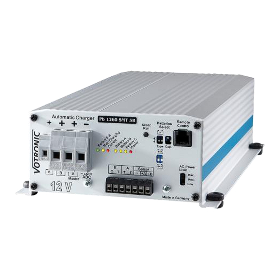
Automatic Charger Pb 1260 SMT 3B
Please read the mounting instructions and the operating manual including the safety
instructions attentively.
Particularly observe page 2 "Safety Regulations and Appropriate Application",
prior to starting connection and start-up.
Fully automatic battery charger with 3 charging ports for high-quality motor homes, intervention and
special purpose vehicles, as well as the marine field.
VOTRONIC chargers of series "Pb - SMT" distinguish by their compact design, low weight (high-frequency switching power
supply, Switch Mode Technology), as well as full charging capacity - even in the event of large fluctuations in the power
supply (undervoltage/overvoltage, sine wave form, frequency).
The intelligent microprocessor charging control with charging programs "IU1oU2oU3" (constant current - constant voltage)
and dynamic charging time calculation ensures automatic, quick and gentle full charging, as well as subsequent 100 %
trickle charge of the connected batteries from any charging state. At the same time, simultaneous supply of 12 V consumer
loads, which are connected in parallel, is ensured or charging of very large batteries (depending on case of application).
Charging Ports and Charging Programs:
1. Main Battery "A (Master)", full charging capacity:
Charging programs 1) - 3) for batteries in lead technology "Lead Acid / AGM 1" - "Motor" - "AGM 2" - "Gel"
Charging Program 4) for batteries in LiFePO4-technology "14.4 V"
Automatic lithium trickle charging 5) of the LiFePO4 battery when the vehicle is stopped (seasonal operation) to
maintain a charging state of 50-80 %, which is advantageous for the battery lifetime. Simultaneous floating of 12 V
consumer loads, such as alarm systems, WLAN etc., as well as the vehicle's starter battery. See page 6.
2. Main Battery "B", full charging capacity, with built-in switchable charging current distributor:
a) Battery type "B = A". Parallel charging B with the same charging programs as battery A 1) – 4). See table 3.
b) Starter battery "B < A". The charging program B is designed for the vehicle starter battery for quick starting ability
and trickle charging by additional components, particularly in case of very high consumer current rates.
3. Signalling/Charging Port "C":
Signalling port 12 V for vehicle engine immobilizer, mains display or as separate auxiliary port 12 V /, 4 A, usable for
support charging and trickle charging of a (lead) vehicle starter battery with overcharge protection. See page 3.
Further Characteristics of the Unit:
The charging voltage is free from peaks and is controlled in such a way, that overcharging of the batteries is excluded.
Fully Automatic Continuous Operation: The charger may be connected continuously to the battery, thus keeping the
full charge. Battery discharge in case of power failure is avoided (separation by safety relay).
Charging aid for deeply discharged (lead) batteries or switched-off LiFePO4 batteries: Gentle preliminary charging of
the (lead-acid, gel, AGM) battery or automatic reactivation of the Li battery, in case of possibly switched-on consumers.
Maintenance Lithium LiFePO4, Auto Wake Up, Maintenance Phase: Regular, automatic activation of the battery cell
equalization charging (balancing) every 10 days to ensure continuous full capacity of the battery.
Battery regeneration in case of extended standstill periods: twice a week to avoid harmful acid accumulation.
Parallel and Floating Operation: In case of simultaneous consumption, the battery will either continue to be charged or
maintained via trickle charging. Calculation and control of the adaptation of the charging times is effected automatically
by the charger.
Unattended Charging: Multiple protection against overload, overheating, overvoltage, short circuit, reverse battery,
incorrect behaviour and back discharge of the battery by electronically controlled gradual reduction down to complete
separation of charger and battery by integrated safety relays.
Connection for Battery Temperature Sensor (Temperature Sensor 825, Order No. 2001, is required):
Lead batteries (acid, gel, AGM): In case of low outside temperatures, full charging of the weak battery is improved by
Charging Capacity 12 V - 12 V / 40 A
Charging Capacity 12 V - 12 V / 50 A
Charging Capacity 12 V - 12 V / 60 A
No. 3124
No. 3125
No. 3126
Advertisement
Table of Contents

Related Manuals for Votronic Pb 1250


Summary of Contents for Votronic Pb 1250
- Page 1 VOTRONIC chargers of series "Pb - SMT" distinguish by their compact design, low weight (high-frequency switching power supply, Switch Mode Technology), as well as full charging capacity - even in the event of large fluctuations in the power supply (undervoltage/overvoltage, sine wave form, frequency).
- Page 2 We do not assume any liability for any damage resulting hereof. The liability exclusion is extended to any service being executed by third, which has not been ordered by us in writing. Service is to be effected exclusively by VOTRONIC Lauterbach.
-
Page 3: Installation Of The Unit
Installation of the Unit: Install the charger near batteries A (Master) and B (short charging cables) at a clean, level and hard mounting surface, which is protected from moisture and humidity. The unit can be installed in any position. Protect the unit from aggressive battery gases. Despite the charger's high efficiency, heat is produced, which is brought out of the casing by means of the built-in fan. - Page 4 Table 1: Recommended lengths of charging cables, cable cross-sections and +fuse capacities: Lengths of Charging Cables – COM Pb 1240 SMT 3B Pb 1250 SMT 3B Pb 1260 SMT 3B as well as +A /+B 2x (3x) 1.0 ... 2.0 m...
- Page 5 Option: Temperature Sensors (Terminals "T T" Battery A and B): The temperature sensors control the battery temperatures and ensure the temperature-depending correction of the charging voltage (automatic "temperature compensation"). Also refer to Charging Programs "with TS", "without TS". Temperature sensor 825, order No. 2001, is required. Recommended to be used for batteries on lead basis (acid/gel/AGM).
- Page 6 Option: Remote Control (Tip Jack "Remote Control") If the charger has been installed in a difficult to access location, the Remote Control S for Automatic Charger (Order No. 2075) can be used for remote control of the charging process (plug-and-go connection cable of 5 m length is included in the delivery scope).
-
Page 7: Unit Settings
It follows the automatic full charging process with the charging program LiFePO4. End of season break. Unit Settings: Table 2: Setting of the battery size A or A+B, (capacity, Ah) by means of the switch "Cap.": Battery Charging Pb 1240 Pb 1250 Pb 1260 Capacity Phase I Selector... -
Page 8: How To Set The Type (Design, Technology) Of Main Battery "A"
How to Set the Type (Design, Technology) of Main Battery "A": 4 Charging programs for the different battery types are stored in the unit. They can be selected by means of the 2 micro slide switches "Type" at the unit front. The control levers of the slide switches are shown in white. -
Page 9: Charging Program For Lifepo4 Batteries
U1=14.40 V U2=13.80 V U3=13.50 V 6-12 h 48 h Continuous Battery Regeneration: 2 x week 1 h Charging program IU1oU2oU3, adapted to closed, gas-tight gel/dryfit batteries VRLA with determined electrolyte, which are generally requiring longer dwell times U1 to achieve particularly high capacity storage and to avoid deep discharge (becoming deaf) of the battery, such as EXIDE, Sonnenschein, "dryfit", Varta, Bosch, Banner,... -
Page 10: Setting Of The Correct Charging Program For Main Battery "B" (Type, Design)
10 - Setting of the Correct Charging Program for Main Battery "B" (Type, Design) Use a small screw-driver to carefully move the 2 slide switches behind the front panel of the unit to the desired position for battery B. Also refer to connection plan (factory adjustment "... - Page 11 11 - Option: Several batteries (battery bank) at one charging port A or B: Parallel charging of two or several batteries of the same voltage (12 V) is admissible. For this purpose, the batteries are connected "in parallel". The capacity values (Ah) are summed up. The total capacity (total Ah) should not exceed the indicated maximum battery capacity (depending on the case of application).
- Page 12 12 - Pilot Lamps: "Battery Full" (Battery (Batteries) fully charged, green)) **: If it is on: Battery (batteries) has (have) been charged to 100 %, trickle charge U2 and storage charge U3, finished. If it is flashing: Main charging process is effected in the charging phase U1, the display of the residual charging time rises gradually from approx.
- Page 13 13 - Chronological Sequence Charging Process Main Port Battery A (Master): A new, complete main charging cycle will be executed: After a power failure or disconnection by means of the mains switch (position "O"). If the battery voltage drops below the reset voltage of 12.75 V / 13.25 V due to high current load beyond the maximum charger current for 30 seconds.
-
Page 14: Operating Instructions
14 - Operating Instructions: Display of the residual charging time: A flashing pilot lamp "Battery Full" allows conclusions concerning the progress of the charging phase U1 (full charging). Directly after the charging phase I (approx. 75 % for lead, approx. 90 % for LiFePO4), the pilot lamp will only be flashing momentarily. - Page 15 15 - Technical Data: 1240 1250 1260 SMT 3B SMT 3B SMT 3B Supply Voltage (Mains Frequency 45 - 65 Hz) AC: (110 V-) 230 V (110 V-) 230 V (110 V-) 230 V Voltage Range Mains Function: 85 V - 270 V, short-time 305 V (5 sec.) Mains Voltage Range for Full Charging Capacity: 190 V - 270 V 190 V - 270 V...
- Page 16 Subject to misprints, errors and technical modification without notice. All rights reserved, particularly the right of reproduction. Copyright VOTRONIC 07/18. Made in Germany by VOTRONIC Electronic-Systeme GmbH & Co. KG, Johann-Friedrich-Diehm-Str. 10, 36341 Lauterbach/GERMANY Phone: +49 (0)6641/91173-0 Fax: +49 (0)6641/91173-20 E-mail: info@votronic.de...
Need help?
Do you have a question about the Pb 1250 and is the answer not in the manual?
Questions and answers