
Related Manuals for Baxi iMPI/H V200 11-16


Summary of Contents for Baxi iMPI/H V200 11-16
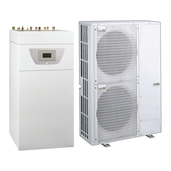
- Page 1 User Guide Reversible air/water "Split Inverter" heat pump iMPI/E V200 4-8 iMPI/H V200 4-8 iMPI/E V200 11-16 iMPI/H V200 11-16...
- Page 2 Dear Customer, Thank you very much for buying this appliance. Please read through the manual carefully before using the product, and keep it in a safe place for later reference. In order to ensure continued safe and efficient operation we recommend that the product is serviced regularly. Our service and customer service organisation can assist with this.
-
Page 3: Table Of Contents
Contents Contents Safety instructions and recommendations ..............5 Safety . - Page 4 Contents Reading out measured values ..............36 Control system sequence .
-
Page 5: Safety Instructions And Recommendations
1 Safety instructions and recommendations Safety instructions and recommendations Safety Operation Danger This appliance can be used by children aged from 8 years and above and persons with reduced physical, sensory or mental capabilities or lack of experience and knowledge if they have been given supervision or instruction concerning use of the appliance in a safe way and understand the haz... -
Page 6: General Instructions
1 Safety instructions and recommendations Domestic wa Draining the appliance: 1. Shut off the domestic cold water inlet. 2. Open a hot water tap in the installation. 3. Open a valve on the safety unit. 4. To drain, open the tap at the base of the tank. The pressure limiter device (safety valve or safety unit) must be regularly oper... -
Page 7: Refrigerant Safety
1 Safety instructions and recommendations Refrigerant safety Warning Refrigerant fluid and pipes: Use only R410A refrigerant fluid to fill the installation. Use tools and pipe components especially designed for use with R410A refrigerant fluid. Use copper pipes deoxidised with phosphorus to carry the refrigerant fluid. -
Page 8: Hydraulic Safety
1 Safety instructions and recommendations Hydraulic safety When making the hydraulic connection, it is imperative that the standards and corresponding local directives be respected. If radiators are connected directly to the heating circuit: install a differential valve between the indoor module and the heating circuit. Fit drainage valves between the indoor module and the heating circuit. -
Page 9: Liabilities
1 Safety instructions and recommendations Remove the casing only to perform maintenance and repair work. Put the casing back in place after maintenance and repair work. The user must make sure the refrigerant pipes are checked annually for leaks for any heat pump with a charge greater than 5 tonnes of CO equivalent. -
Page 10: Symbols Used
2 Symbols used Symbols used Symbols used in the manual This manual uses various danger levels to draw attention to special instructions. We do this to improve user safety, to prevent problems and to guarantee correct operation of the appliance. Danger Risk of dangerous situations that may result in serious personal injury. - Page 11 2 Symbols used Fig.2 Symbols used on the connection 1 Sensor cable - low voltage label 2 Power supply cable 230 V / 400 V 3 Heating circuit flow 4 Circuit B flow 5 Heating circuit return 6 Circuit B return (optional) G1"...
-
Page 12: Technical Specifications
3 Technical specifications Technical specifications Homologations 3.1.1 Directives This product complies with the requirements of the following European Directives and Standards: Pressure Equipment Directive 2014/68/EU Low Voltage Directive 2014/35/EU Generic standard: EN 60335-1 Relevant standards: EN 60335-2-21, EN 60335-2-40 Electromagnetic Compatibility Directive 2014/30/EU Generic standards: EN 61000-6-3, EN 61000-6-1 Relevant Standard: EN 55014 This product conforms to the requirements of European Directive... - Page 13 3 Technical specifications Measurement type Unit AWHP 4.5 AWHP 6 AWHP 8 AWHP 11 AWHP 11 AWHP 16 AWHP 16 MR-3 MR-2 MR-2 TR-2 MR-2 TR-2 Absorbed electrical pow 0.90 1.38 1.82 2.45 2.45 3.47 3.47 Nominal water flow rate 0.80 1.00 1.36...
-
Page 14: Domestic Hot Water Tank
2.72 2.72 domestic hot water (COP 3.2.3 Heat pump weight Tab.9 Indoor module Indoor module Unit iMPI/E V200 4-8 iMPI/H V200 4-8 iMPI/E V200 11-16 iMPI/H V200 11-16 Weight (empty) Total weight with water Tab.10 Outdoor unit Outdoor unit Unit AWHP 4.5 MR... - Page 15 3 Technical specifications Product name iMPI V200 iMPI V200 iMPI V200 AWHP 4.5 MR AWHP 6 MR-3 AWHP 8 MR-2 Brine-to-water heat pump Low-temperature heat pump Equipped with a supplementary heater Heat pump combination heater Prated Rated heat output under average conditions Prated Rated heat output under colder conditions Prated...
- Page 16 3 Technical specifications Product name iMPI V200 iMPI V200 iMPI V200 AWHP 4.5 MR AWHP 6 MR-3 AWHP 8 MR-2 Annual energy consumption under warmer condi 1249 1492 1904 tions Rated air flow rate, outdoors for air-to-water heat — 2100 2100 3300 pumps...
-
Page 17: Circulating Pump
3 Technical specifications Product name iMPI V200 iMPI V200 AWHP 11 MR-2 AWHP 16 MR-2 AWHP 11 TR-2 AWHP 16 TR-2 = operation limit temperature COPd 1.20 1.35 Operation limit temperature for air-to-water heat °C pumps WTOL Heating water operating limit temperature °C Electrical power consumption Off mode... -
Page 18: Description Of The Product
4 Description of the product Description of the product Main components Fig.3 Main components 1 Control panel 2 ON/OFF button Operating principle The heat pumps in the iMPI V200 range extract the heat found in the air to restore it to the heating and/or domestic hot water circuit via the refrigerant fluid. -
Page 19: Control Panel Description
4 Description of the product Fig.4 General operating principle MW-6000391-1 1 Evaporator (fin battery in the outdoor unit) 5 Electrical energy 2 Compressor 6 Heating water 3 Condenser (plate exchanger in the indoor module) 7 Energy flow 4 Electronic expansion valve 8 Heat recovered from the environment Control panel description 4.3.1... - Page 20 4 Description of the product Electrical back-up Fig.7 Stage 1 of the electrical back-up Stage 2 of the electrical back-up Status of the Compressor Fig.8 Steady symbol: compressing running Operating modes Fig.9 Steady symbol: heating function enabled Flashing symbol: heating production running Steady symbol: domestic hot water function enabled Flashing symbol: domestic hot water production running Heating or cooling function disabled...
- Page 21 4 Description of the product Sub-Menu CLOCK PCB selection menu: access to information on the additional PCBs connected Display of PCB names Fig.13 The name of the PCB for which the parameters are displayed is scrolling across the screen on 3 characters. Fig.14 Central unit PCB EHC-04: direct circuit and domestic hot water ...EHC / --04...
-
Page 22: Operation
5 Operation Operation Using the user interface 5.1.1 Browsing in the menus Press any key to turn on the backlight for the control panel screen. If no key is pressed within 3 minutes, the control panel backlight will go out. Fig.19 Press the 2 right-hand keys together to access the different menus: Tab.13... -
Page 23: Shutdown
5 Operation Shutdown 5.3.1 Switching off the heating Important Heating mode can be managed via the TIME PROG sub-menu dedicated to timer programming. Important If the heating function is shut off, then the cooling will also be shut off. Fig.23 1. -
Page 24: Stopping Domestic Hot Water Production
5 Operation 5.3.2 Stopping domestic hot water production Important Domestic hot water production can be managed via the TIME PROG sub-menu dedicated to timer programming. Fig.26 1. Go to stop mode by pressing the key. MW-5000135-3 Fig.27 2. Select domestic hot water production mode pressing the key. -
Page 25: Frost Protection
5 Operation Frost Protection If the temperature of the heating water in the heat pump falls too much, the integrated protection device switches itself on. This device functions as follows: If the water temperature is lower than 5°C, the circulating pump starts If the water temperature is lower than 3°C, the back-up starts up. -
Page 26: Settings
6 Settings Settings Modifying the User parameters Caution Altering the factory settings may impair operation of the appliance. Fig.29 1. Go to the User menu. 2. Select the desired sub-menu by pressing the key. 3. Confirm the selection by pressing the key. - Page 27 6 Settings Parameter Description Factory setting Factory setting CIRCA CIRCB CP082 User Room Setpoint Zone Activity temperature in activity zone 3 Can be set from 5 °C to 30 °C CP083 User Room Setpoint Zone Activity temperature in activity zone 4 Can be set from 5 °C to 30 °C CP084 User Room Setpoint Zone Activity temperature in activity zone 5...
-
Page 28: User \Dhw Menu
6 Settings Parameter Description Factory setting Factory setting CIRCA CIRCB CP570 Time Program of the zone selected by the user 0 = programme 1 1 = programme 2 2 = programme 3 CP660 Choice icon to display this zone 0 =None 1 =All 2 =Bedroom 3 =Livingroom... -
Page 29: User \Hmi Menu
6 Settings Parameter Description Factory setting AP073 Outdoor temperature: upper limit for heating SUMMER / WINTER set point switch: Can be set from 15 °C to 30.5 °C AP074 The heating is stopped. Hot water is maintained. Force Summer Mode SUMMER override: 0 = off 1 = on... -
Page 30: Counters /Time Prog / Clock Menus
6 Settings Tab.20 Parameter Description Factory setting HP062 Energy cost in Hybrid electricity cost in high tarif 0.13 €/kWh Can be set from 0.01 to 2.50 €/kWh HP063 Energy cost in Hybrid electricity cost in low tarif 0.09 €/kWh Can be set from 0.01 to 2.50 €/kWh HP064 Cost of fossil energy (oil or gas) - price per litre or per m3 0.90 €/kWh... -
Page 31: Counters, Time Prog, Clock \Circa, Circb And Dhw Menus
6 Settings Parameter Description Unit EHC-04 SCB04-B DC003 Number of hours during which the diverting valve hours is in DHW position DC004 Number of compressor start-ups during domestic hot water production DC005 Number of compressor start-ups PC002 Number of compressor start-ups PC003 Number of compressor operating hours hours... -
Page 32: Setting The Parameters
6 Settings Setting the parameters 6.4.1 Setting the room temperature set point in comfort mode Important The room temperature set point can be managed via the TIME PROG sub-menu dedicated to timer programming. Important To set the room set point temperature in reduced mode, it is necessary to set the CP080 parameter available in the User menu. -
Page 33: Activating Manual Forcing For Heating
6 Settings Important The heat pump switches to cooling automatically when the outdoor temperature is +2 °C greater than the summer/winter switching set point temperature (22 °C). The forced cooling function is used to have cooling regardless of the outdoor temperature. -
Page 34: Setting The Timer Programming
6 Settings Fig.40 2. Set the value of the heating water temperature set point by pressing key. 3. Confirm the new value of the heating water temperature set point by pressing the key. 4. Go back to the main display by pressing the key. - Page 35 6 Settings Fig.45 7. Set the start time for the period by pressing the key. 8. Confirm the selection by pressing the key. MW-5000142-2 Fig.46 9. Select the status that corresponds to the period by pressing key. Status for periods Description comfort mode reduced mode...
-
Page 36: Reading Out Measured Values
7 Reading out measured values Reading out measured values The measured values are available in the Information menu of the different PCBs. Certain parameters are displayed: according to certain system configurations, according to the options, circuits or sensors actually connected. Tab.26 Choosing the menu Counters... -
Page 37: Control System Sequence
7 Reading out measured values Parameter Description Unit EHC-04 SCB04-B DM001 Domestic Hot Water tank temperature (bottom sensor) °C DM006 Domestic Hot Water tank temperature (top sensor) DM009 Automatic/derogation status of Domestic Hot Water °C mode: 0 =Scheduling 1 =Manual 2 =Antifrost 3 =Temporary DM029... - Page 38 7 Reading out measured values Status Appliance: AM012 parameter Appliance sub status: AM014 parameter 3= operating in heating mode 30= normal operation The compressor or the back-ups are running. 31= internal set point limited If the heating set point on the heat pump differs from the system set point. 60= pump post-operation Heat pump and back-up shut-down, system pump operation.
- Page 39 7 Reading out measured values Status Appliance: AM012 parameter Appliance sub status: AM014 parameter 4= operating in domestic hot water mode 30= normal operation The compressor or the back-ups are running. 31= internal set point limited If the heating set point on the heat pump differs from the system set point. 60= pump post-operation Heat pump and back-up shut-down, system pump operation.
- Page 40 7 Reading out measured values Status Appliance: AM012 parameter Appliance sub status: AM014 parameter 8= controlled compressor shut-down Controlled Stop 00= off: the heating or cooling set point has been reached 01= anti-short cycle The heating set point has been reached. The compressor is not authorised to restart.
- Page 41 7 Reading out measured values Status Appliance: AM012 parameter Appliance sub status: AM014 parameter Load test CH max 30= normal operation. The compressor or the back-ups are running. 31= internal set point limited If the heating set point on the heat pump differs from the system set point. 60= pump post-operation Heat pump and back-up shut-down, system pump post-operation.
- Page 42 7 Reading out measured values Status Appliance: AM012 parameter Appliance sub status: AM014 parameter Frost protection 30= normal operation The compressor or the back-ups are running. 31= internal set point limited If the heating set point on the heat pump differs from the system set point. 60= pump post-operation Heat pump and back-up shut-down, system pump post-operation.
-
Page 43: Maintenance
8 Maintenance Maintenance General Maintenance operations are important for the following reasons: To guarantee optimum performance. To extend the life of the equipment. To provide an installation which offers the user optimum comfort over time. Caution Only qualified professionals are authorised to carry out maintenance work on the heat pump and the heating system. -
Page 44: Troubleshooting
9 Troubleshooting Troubleshooting Error messages Fig.47 Resetting the control panel allows the appliance to be restarted. The message appears when a fault code is detected. After resolving the problem, pressing the key resets the appliance's functions and thus eradicates the fault. If several faults occur, they are displayed one after the other. -
Page 45: Fault Codes
9 Troubleshooting Error Message Description code H02.23 System flow error System water flow error active Flow problem Insufficient flow: open a radiator valve. The circuit is clogged: Check that the filters are not obstructed and clean them if necessary. Clean and flush the installation, No circulation: Check that the valves and thermostatic valves are open, Check that the circulating pump is working,... -
Page 46: Accessing The Error Memory
9 Troubleshooting When one of the following codes is displayed and the hybrid system cannot restart automatically, contact a maintenance technician. Tab.32 List of alarm codes Error code Message Description A02.06 Water Press Warning Water Pressure Warning active A02.18 OBD Error Object Dictionary Error A02.22 System flow warning... -
Page 47: Fault Finding
9 Troubleshooting Fault finding Problems Probable causes Corrections The radiators are cold. The heating set point tem Increase the value of the room temperature set point or, if a room ther perature is too low. mostat is connected, increase the temperature on it. The heating mode is deac... -
Page 48: 10 Decommissioning And Disposal
10 Decommissioning and disposal 10 Decommissioning and disposal 10.1 Decommissioning procedure To decommission the heat pump temporarily or permanently: 1. Contact the installer. 10.2 Disposal and recycling Fig.53 Warning Removal and disposal of the heat pump must be carried out by a qualified professional in accordance with prevailing local and national regulations. -
Page 49: 11 Environmental
11 Environmental 11 Environmental 11.1 Energy savings Energy-saving advice: Do not block ventilation outlets. Do not cover the radiators. Do not hang curtains in front of the radiators. Install reflective panels behind the radiators to prevent heat losses. Insulate the pipes in rooms that are not heated (cellars and lofts). Close the radiators in rooms not in use. -
Page 50: 12 Warranty
12 Warranty 12 Warranty 12.1 General We would like to thank you for buying one of our appliances and for your trust in our product. In order to ensure continued safe and efficient operation, we recommend that the product is regularly inspected and maintained. Your installer and our service department can assist with this. -
Page 51: 13 Appendix
13 Appendix 13 Appendix 13.1 Product fiche Tab.33 Product data sheet for heat pump combination heaters iMPI V200 iMPI V200 iMPI V200 AWHP 4.5 AWHP 6 MR-3 AWHP 8 MR-2 Space heating - Temperature application Medium Medium Medium Water heating - Declared load profile Seasonal space heating energy efficiency class under average climate conditions Water heating energy efficiency class under average climate... -
Page 52: Product Fiche - Temperature Controls
13 Appendix iMPI V200 iMPI V200 AWHP 11 MR-2 AWHP 16 MR-2 AWHP 11 TR-2 AWHP 16 TR-2 Seasonal space heating energy efficiency under average climate condi tions Water heating energy efficiency under average climate conditions 106.00 106.00 Sound power level L indoors Ability to function during off-peak hours Rated heat output, under colder - warmer climate conditions... - Page 53 13 Appendix Fig.54 Package fiche for medium-temperature heat pumps indicating the space heating energy efficiency of the package Seasonal space heating energy effi ciency of heat pump ‘I’ Temperature control Class I = 1%, Class II = 2%, Class III = 1.5%, Class IV = 2%, Class V = 3%, Class VI = 4%, from fi...
- Page 54 13 Appendix Tab.36 Weighting of medium temperature heat pumps II, package without hot water storage tank II, package with hot water storage tank Prated / (Prated + Psup) (1)(2) 1.00 1.00 0.70 0.63 0.45 0.30 0.25 0.15 0.15 0.06 0.05 0.02 0.02 ≥...
-
Page 55: Package Fiche - Combination Heaters (Boilers Or Heat Pumps)
13 Appendix 13.4 Package fiche - Combination heaters (boilers or heat pumps) Fig.55 Package fiche for combination heaters (boilers or heat pumps) indicating the water heating energy efficiency of the package Water heating energy effi ciency of combination heater ‘I’ Declared load profi... - Page 56 13 Appendix iMPI V200 7700954 - v03 - 13082018...
- Page 57 13 Appendix 7700954 - v03 - 13082018 iMPI V200...
- Page 58 13 Appendix iMPI V200 7700954 - v03 - 13082018...
- Page 59 © Copyright All technical and technological information contained in these technical instructions, as well as any drawings and technical descriptions supplied, remain our property and shall not be multiplied without our prior consent in writing. Subject to alterations.
- Page 60 7700954 - v03 - 13082018 7700954-001-03...
Need help?
Do you have a question about the iMPI/H V200 11-16 and is the answer not in the manual?
Questions and answers