Table of Contents
Advertisement
Product Information on the Reference Manual
Programmable Logic Controllers S7-300 Module Data Release 3
1
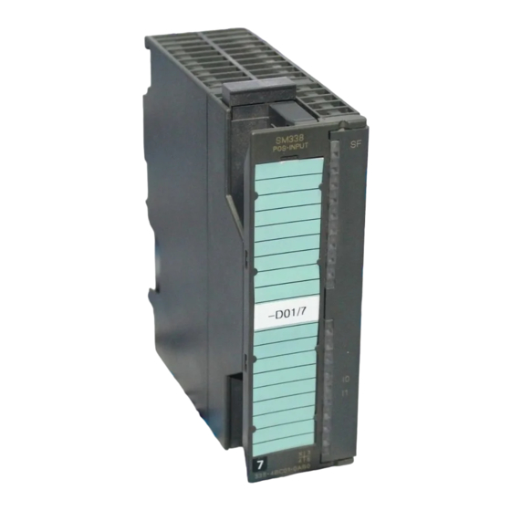
Position Decoder Module SM 338; POS-INPUT;
(6ES7338-4BC01-0AB0)
Order number
6ES7338-4BC01-0AB0
Characteristics
The position decoder module SM 338; POS-INPUT is distinguished by the
following features:
• 3 inputs for the connection of maximum three absolute value encoders (SSI)
and 2 digital inputs to freeze the encoder values
• Direct reaction possible to encoder values in moving systems
• Processing of acquired encoder values of the SM 338 in user program
• Supports clocked operation
• Type of encoder value acquisition (see chapter 1.1.2.1) can be selected:
– Free running
– Clocked
• 24 VDC rated input voltage
• Non-isolated against the CPU
• Fast mode selectable; with faster encoder recording and compressed
checkback interface
Fast mode is available as of SM 338; POS-INPUT firmware version V2.0.0 and
as of STEP 7 V5.3+SP2 selectable.
Copyright 2005 by Siemens AG
A5E00409892-01
Advertisement
Table of Contents

Related Manuals for Siemens POS INPUT


Summarization of Contents
Programmable Logic Controllers S7-300 Module Data Release 3
Position Decoder Module SM 338; POS-INPUT; (6ES7338-4BC01-0AB0)
Product information for the SM 338 POS-INPUT module, including its order number and key features.
Supported encoder types
Lists the types of absolute value encoders (SSI) supported by the SM 338 module.
Supported data formats
Details the data formats (gray code and binary code) supported by the SM 338.
Firmware update
Explains the process and importance of updating the SM 338 firmware using STEP 7.
1.1 Synchronous Operation
Hardware requirements
Lists the necessary hardware components for the synchronous operation of the SM 338.
Characteristics
Describes how the SM 338 operates in synchronous mode, including data exchange and cycle synchronization.
1.1.1 Terminal Connection Diagram and Block Diagram
Wiring rules
Outlines essential rules and guidelines for correctly wiring the SM 338 module and its components.
1.1.2 Functions of the SM 338; POS INPUT
1.1.2.1 Encoder value acquisition
Explains how the SM 338 acquires encoder values, differentiating between synchronous and free-running modes.
Free running encoder value acquisition
Details the process of acquiring encoder values asynchronously at the end of the parameterized monoflop time.
Synchronous encoder values acquisition
Describes synchronous acquisition synchronized to the PROFIBUS DP cycle, initiated by the SM 338.
1.1.2.2 Gray/Dual Converter
Explains the conversion between Gray code and Dual code for encoder values in the SM 338.
1.1.2.3 Transferred Encoder Value and Normalization
Covers the transferred encoder value and the settings required for its detection and normalization.
Example of normalization of an encoder value
Illustrates the process of normalizing encoder values in STEP 7, showing bit manipulation.
1.1.2.4 Freeze Function
Details the freeze function, its coupling to digital inputs, and how it captures encoder values.
Ending the freeze function
Explains how to end the freeze function and acknowledge it, restoring normal encoder value updates.
1.1.3 SM 338; POS-INPUT Parameterization
SM 338; POS-INPUT Parameterization
Describes the process of parameterizing the SM 338 module using STEP 7 in CPU STOP mode.
Parameters of the SM 338; POS-INPUT
Provides an overview of settable parameters, their ranges, default settings, and notes for the SM 338.
1.1.4 SM 338; POS-INPUT Addressing
Data range for the encoder values
Defines the addressing for encoder values, inputs, and outputs of the SM 338 within STEP 7 configuration.
Structure of the double data word in Standard Mode
Explains the structure of the double data word for each encoder input in standard mode, including sensor value and freeze bit.
Structure of the double data word in Fast Mode
Details the structure of the double data word in fast mode, including sensor value and status digital inputs.
Output Address im Standard Mode
Shows the output address structure for acknowledging the freeze function in standard mode.
1.1.5 Diagnosis of the SM 338; POS-INPUT
Actions following diagnostic message in STEP 7
Describes the actions taken by the CPU and module when a diagnostic message is triggered.
Reading out diagnostic messages
Explains how to read detailed diagnostic messages from the SM 338 using SFCs in the user program.
Diagnostic message via SF LED
Details how the SF LED on the module indicates errors and faults, including external ones.
Diagnostic messages of the SM 338; POS INPUT
Provides an overview of diagnostic messages for the SM 338, listing message types, LED indicators, and scope.
Causes of errors and remedial measures
Lists diagnostic messages, their possible causes, and recommended remedial actions for the SM 338.
1.1.6 Interrupts of the SM 338; POS INPUT
Enabling interrupts
Explains that interrupts are not preset and require parameter assignment in STEP 7 to be enabled.
Diagnostic interrupt
Describes how diagnostic interrupts report error events and how the CPU processes them via OB 82.
1.1.7 Technical Specifications of the 338; POS-INPUT
Dimensions and Weight
Lists the physical dimensions (B x H x T) and approximate weight of the SM 338 module.
Voltages, Currents, Potentials
Details the rated load voltage, reverse polarity protection, encoder supply, and current dissipation of the SM 338.
Encoder inputs POS INPUT 0 to 2
Provides technical data for SSI data and clock, including position decoding, data transfer rate, and cable length.
Inaccuracy of the encoder value
Covers inaccuracy metrics like maximum/minimum age and jitter for free-running and fast mode encoder value acquisition.
Free running encoder value acquisition
Specifies inaccuracy metrics (age, jitter) for free running encoder value acquisition in standard mode.
Free-wheeling sensor value detection (Fast Mode)
Specifies inaccuracy metrics (age, jitter) for encoder value acquisition in fast mode.
Synchronous encoder value acquisition
Defines the age metric for encoder values acquired synchronously to the PROFIBUS DP cycle.
Inaccuracy of the frozen encoder value (freeze)
Details inaccuracy metrics (maximum/minimum age, jitter) for frozen encoder values in free running mode.
Isochrone time of the module
Provides isochrone time values (TWE, TWA, ToiMin, TDPMin) for standard and fast modes of the SM 338.
Need help?
Do you have a question about the POS INPUT and is the answer not in the manual?
Questions and answers