Table of Contents
Advertisement
Quick Links
SENTRON
Expansion module
PAC RS485
Manual
02/2008
A5E02091800B-01
Introduction
Safety notes
Description
Assembling
Parameter
assignment/Addressing
Configuration
Service and maintenance
Alarm, error, and system
messages
Troubleshooting/FAQs
Technical data
Dimension drawings
Application examples
Appendix
ESD guidelines
List of abbreviations
1
2
3
4
5
6
7
8
9
10
11
12
A
B
C
Advertisement
Table of Contents

Related Manuals for Siemens SENTRON PAC RS485


Summary of Contents for Siemens SENTRON PAC RS485
- Page 1 Introduction Safety notes Description SENTRON Assembling Expansion module PAC RS485 Parameter assignment/Addressing Configuration Manual Service and maintenance Alarm, error, and system messages Troubleshooting/FAQs Technical data Dimension drawings Application examples Appendix ESD guidelines List of abbreviations 02/2008 A5E02091800B-01...
- Page 2 Trademarks All names identified by ® are registered trademarks of the Siemens AG. The remaining trademarks in this publication may be trademarks whose use by third parties for their own purposes could violate the rights of the owner.
-
Page 3: Table Of Contents
Table of contents Introduction..............................7 Purpose of this document ......................7 Orientation aids ..........................7 Scope of supply ..........................8 Contents of the CD for the SENTRON PAC Power Monitoring Device.........8 Technical support...........................9 Further documentation.........................10 Safety notes............................. 11 Safety notes ..........................11 Description............................... 13 Area of application ........................13 Features ............................13 Tasks............................14... - Page 4 Table of contents 5.1.9 Modbus command parameters ....................51 5.1.10 MODBUS communication parameter with the function codes 0x03, 0x04 and 0x10 ....52 5.1.11 Modbus device information with the function codes 0x03, 0x04 and 0x10......... 53 5.1.12 MODBUS standard device identification with the function code 0x2B ........55 5.1.13 Parameters and function codes supported by the broadcast commands........
- Page 5 Table of contents Tables Table 1-1 Contacts in your region - worldwide....................9 Table 1-2 Online service and support ......................9 Table 1-3 Technical Support ........................10 Table 5-1 Structure of the message frame....................29 Table 5-2 Supported function codes ......................31 Table 5-3 MODBUS exception codes ......................33 Table 5-4 Available measured variables ......................34 Table 5-5...
- Page 6 Table of contents Table 10-2 Mechanical data for the PAC RS485 expansion module............68 Table 10-3 Electrical data for the PAC RS485 expansion module ............... 69 Table 10-4 Ambient and environmental conditions ..................69 Table 10-5 Technical data for the communication interface ................. 70 Table 10-6 Connection types with associated conductor cross-sections............
-
Page 7: Introduction
Introduction Purpose of this document This manual is intended for: ● Planners ● Plant operators ● Commissioning engineers ● Service and maintenance personnel This manual contains: ● Details of the design of the PAC RS485 expansion module ● Permissible conditions of use for the PAC RS485 expansion module Required basic knowledge General knowledge in the fields of automation and electrical engineering is required to understand this manual. -
Page 8: Scope Of Supply
Introduction 1.3 Scope of supply Scope of supply Description The package includes: ● The PAC RS485 expansion module including 2 permanent screws ● Terminal block including 6 permanent screws ● The operating instructions for the PAC RS485 expansion module Contents of the CD for the SENTRON PAC Power Monitoring Device CD contents The SENTRON PAC CD includes the following files: ●... -
Page 9: Technical Support
Contacts in your region can provide support worldwide. Table 1-1 Contacts in your region - worldwide Utility Address, number Internet: Service and support (http://www.siemens.com/automation/service&support) under "Contact > Contacts worldwide" Support address: SIEMENS AG A&D CD MM1 Gleiwitzerstr. 555 D-90475 Nuremberg Online support This comprehensive information system is available day and night via the Internet. -
Page 10: Further Documentation
Phone: +49 (0)180-50-50-222 Fax: +49 (0)180-50-50-223 Internet: Support request (http://www.siemens.com/automation/support-request) Further documentation Overview You can find further details in the following manuals: ● Manual for the SENTRON PAC Power Monitoring Device ● Operating instructions for the SENTRON PAC Power Monitoring Device ●... -
Page 11: Safety Notes
Safety notes Safety notes General safety notes DANGER Danger! High voltage Will cause death or serious injury. Turn off and lock out all power supplying this device before working on this device. PAC RS485 Manual, 02/2008, A5E02091800B-01... - Page 12 Safety notes 2.1 Safety notes PAC RS485 Manual, 02/2008, A5E02091800B-01...
-
Page 13: Description
Description Area of application The PAC RS485 expansion module is designed for use with a SENTRON PAC Power Monitoring Device. Area of application of the PAC RS485 expansion module The PAC RS485 expansion module connects the SENTRON PAC Power Monitoring Device to the RS 485 bus. -
Page 14: Tasks
Description 3.3 Tasks ● Configuration via: – the SENTRON PAC Power Monitoring Device – the Ethernet interface – the RS 485 interface ● Unicast messages ● Broadcast commands with address 0 to the MODBUS slaves See also Parameters and function codes supported by the broadcast commands (Page 55) Tasks Description The tasks of the PAC RS485 expansion module are as follows:... -
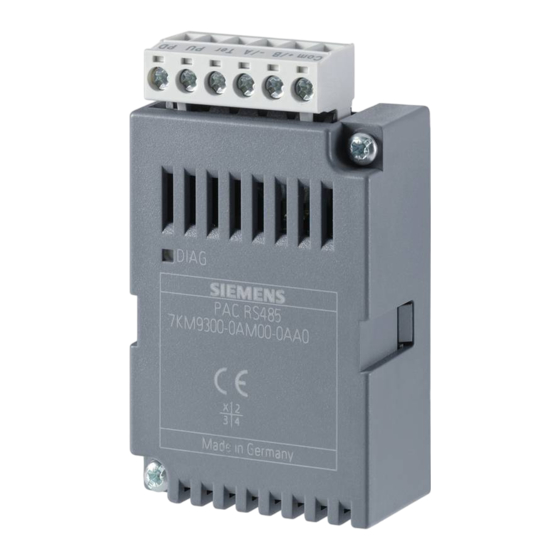
Page 15: Structure
Description 3.4 Structure Structure Structure of the PAC RS485 expansion module Figure 3-1 Schematic view of the side and front of the PAC RS485 expansion module Terminal block Screw for mounting the PAC RS485 expansion module on the SENTRON PAC Power Monitoring Device Ventilation slots PAC RS485... -
Page 16: Firmware
Description 3.5 Firmware Figure 3-2 Schematic view of the rear of the PAC RS485 expansion module Terminal block Screw for mounting the PAC RS485 expansion module on the SENTRON PAC Power Monitoring Device Guide pins; their guide for correct position ensures that the PAC RS485 expansion module is plugged into the SENTRON PAC Power Monitoring Device correctly Pins Firmware... -
Page 17: Bus And Master
Description 3.6 Bus and master Bus and master Restrictions The following restrictions apply for the use of a bus and a master: ● You must use only broadcast commands that agree in syntax and meaning with the broadcast commands supported by the Power Monitoring Device. ●... - Page 18 Description 3.6 Bus and master PAC RS485 Manual, 02/2008, A5E02091800B-01...
-
Page 19: Assembling
Assembling Procedure for installation and commissioning The following system configuration information must be available: ● Installation location of the device ● Baud rate ● Planned address of the PAC RS485 expansion module Procedure 1. Mount the SENTRON PAC Power Monitoring Device and the PAC RS485 expansion module. -
Page 20: Unpacking
● Make sure that the package contents are complete. ● Check the module for external damage. Please contact your Siemens sales partner in the following cases: ● The packaging is damaged ● The contents of the package are not complete ●... -
Page 21: Assembly
Assembling 4.3 Assembly Assembly NOTICE Condensation Sudden fluctuations in temperature can lead to condensation. Condensation can affect the function of the PAC RS485 expansion module. Store the PAC RS485 expansion module in the operating room for at least 2 hours before commencing installation. Tools To install the PAC RS485 expansion module you will need the following tool: ●... -
Page 22: Figure 4-1 Schematic View Of Assembling The Pac Rs485 Expansion Module
Assembling 4.3 Assembly Figure 4-1 Schematic view of assembling the PAC RS485 expansion module 1. Ensure safe isolation from supply. 2. Discharge yourself. 3. Mount the SENTRON PAC Power Monitoring Device. 4. Connect the current terminals and voltage terminals to the SENTRON PAC. 5. -
Page 23: Connecting
Assembling 4.4 Connecting NOTICE Damage due to moisture Moisture or wetness can affect the operating capability of the PAC RS485 expansion module. Make sure that no moisture or wetness can find its way into the PAC RS485 expansion module. Clean the PAC RS485 expansion module using a dry, lint-free cloth only. -
Page 24: Figure 4-2 Block Diagram: General Topology Of The Twisted-Pair Cable
Assembling 4.4 Connecting Figure 4-2 Block diagram: General topology of the twisted-pair cable B signal; D1 A signal; D0 Common = Ground (Line) Termination = bus terminating resistor Pull-up resistor Pull-down resistor Figure 4-3 Terminal assignment 1. Connect the cables to the appropriate screw terminals on the terminal block. You can find the assignments of the terminals in the figure "Terminal assignment". -
Page 25: Figure 4-4 Terminal Assignment With Terminating Resistor
Assembling 4.4 Connecting Figure 4-4 Terminal assignment with terminating resistor NOTICE Incorrect bus terminator If you switch more than two bus terminating resistors on one bus, this can result, for example, in signal reflections that interfere with communication on the bus. Never attach more than two bus terminators to one bus. -
Page 26: Measures To Be Performed Prior To Start-Up
Assembling 4.5 Measures to be performed prior to start-up Measures to be performed prior to start-up CAUTION Never start up damaged modules Damaged components can impair and endanger operation. Never use damaged components. NOTICE Condensation Store the device in the service room for at least two hours before applying voltage to the device for the first time. -
Page 27: Disassembly
Assembling 4.6 Disassembly Disassembly Disassembling 1. Ensure safe isolation from supply. 2. Observe the ESD Guidelines. Discharge yourself. Handle the PAC RS485 expansion module by the plastic housing only. 3. Remove the terminal block from the expansion module, or detach the cable from the terminal block. - Page 28 Assembling 4.6 Disassembly PAC RS485 Manual, 02/2008, A5E02091800B-01...
-
Page 29: Parameter Assignment/Addressing
Parameter assignment/Addressing MODBUS RTU 5.1.1 Structure of the job message frame Structure Data traffic between the master and the slave and between the slave and the master begins with the address of the slave. The job message frame consists of the following elements: 1. -
Page 30: Character Frame
Parameter assignment/Addressing 5.1 MODBUS RTU Validity of the message frame Gaps in the message frame are filled with 0xFFFFFFFF. FFFFFFFF means the message frame contains no measured values. This means it is invalid. If the message frame has a different content it is in principle valid. See also Function codes (Page 31) 5.1.2... -
Page 31: Function Codes
Parameter assignment/Addressing 5.1 MODBUS RTU The Least Significant Bit (LSB) is sent at the start of the eight data bits, and the Most Significant Bit (MSB) is sent at the end. See also Configuration of the PAC RS485 expansion module on the SENTRON PAC3200 Power Monitoring Device (Page 58) 5.1.3 Function codes... - Page 32 Parameter assignment/Addressing 5.1 MODBUS RTU FC 04 You can read out device registers with this function code. Number of requested registers: At least 1 to maximum 125 Corresponding exception codes: 01, 02, 03 or 04 Corresponding error code: 0x84 FC 06 This function code overwrites a slave register with a new value.
-
Page 33: Exception Codes
Parameter assignment/Addressing 5.1 MODBUS RTU 5.1.4 Exception codes Overview Table 5-3 MODBUS exception codes Exception codes Name Meaning Remedy Illegal Illegal function: Check which function Function codes are supported. The function code in the • request is not a permissible action for the slave. -
Page 34: Table 5-4 Available Measured Variables
Parameter assignment/Addressing 5.1 MODBUS RTU NOTICE Error in the case of inconsistent access to measured values Please ensure the start offset of the register is correct when making read accesses. Please ensure the start offset and the number of registers are correct when making write accesses. - Page 35 Parameter assignment/Addressing 5.1 MODBUS RTU Offset Number of Name Format Unit Value range Access registers Average Voltage V Float ph-ph Average Current Float Total Apparent Power Float Total Active Power Float Total Reactive Power Float Total Power Factor Float Amplitude Unbalance - Voltage Float 0 ...
- Page 36 Parameter assignment/Addressing 5.1 MODBUS RTU Offset Number of Name Format Unit Value range Access registers Max. Total Reactive Power Float Maximum Total Power Factor Float Minimum Voltage V Float Minimum Voltage V Float Minimum Voltage V Float Min. Voltage V Float Min.
- Page 37 Parameter assignment/Addressing 5.1 MODBUS RTU Offset Number of Name Format Unit Value range Access registers Counter All Parameter Changes Unsigned long Counter Limit Violations Demand Active Power - Import Float Demand Reactive Power - Import Float Demand Active Power - Export Float Demand Reactive Power - Export Float...
-
Page 38: Structure
Parameter assignment/Addressing 5.1 MODBUS RTU 5.1.6 Structure 5.1.6.1 Structure - Digital input status and digital output status with the function codes 0x03 and 0x04 The following are available via MODBUS: ● "Status of the Digital Inputs" ● "Status of the Digital Outputs" Input status and output status of the SENTRON PAC Power Monitoring Device Table 5-5 Structure - Status of the digital inputs and status of the digital outputs... -
Page 39: Structure - Limit Values With Function Codes 0X03 And 0X04
Parameter assignment/Addressing 5.1 MODBUS RTU 5.1.6.3 Structure - Limit values with function codes 0x03 and 0x04 Structure of the limit values Table 5-7 Modbus Offset 203, Register 2: Limit Violations Byte Status Bit mask Value range Access Limit 0 0x00000001 No limit violation Limit 1 0x00000002... -
Page 40: Modbus Settings With The Function Codes 0X03, 0X04 And 0X10
Parameter assignment/Addressing 5.1 MODBUS RTU Offset Number of Name Format Value range Access registers No synchronization pulse Device Configuration menu is active Voltage overload Current overload Digital input 0 Digital output 0 See also Modbus measured variables with the function codes 0x03 and 0x04 (Page 33) Structure - Digital input status and digital output status with the function codes 0x03 and 0x04 (Page 38) Structure - Device diagnostics and device status with the function codes 0x03 and 0x04... -
Page 41: Table 5-10 Settings Parameter For The Digital Input
Parameter assignment/Addressing 5.1 MODBUS RTU Offset Number of Name Unit Format Value range Access registers 50019 Zero point suppression float 0.0 ... 10.0 level (% rated current) 50021 Demand Period Min. unsigned long 1 ... 60 50023 Synchronization unsigned long No synchronization Synchronization via bus... -
Page 42: Table 5-12 Settings Parameter For Language, Phase Labels And Universal Counters Source
Parameter assignment/Addressing 5.1 MODBUS RTU Offset Number of Name Unit Format Value range Access registers 50037 "Limit violation" mode unsigned long Limit Logic Limit 0 Limit 1 Limit 2 Limit 3 Limit 4 Limit 5 50041 "Energy pulse" mode unsigned long Import kWh Export kWh Import kvarh... -
Page 43: Table 5-13 Settings Parameter For The Display
Parameter assignment/Addressing 5.1 MODBUS RTU Table 5-13 Settings parameter for the display Offset Number of Name Unit Format Value range Access registers 50053 Refresh time unsigned long 330 ... 3000 50055 Contrast unsigned long 1 ... 10 50057 Backlight level - Normal unsigned long 0 ... -
Page 44: Table 5-15 Settings Parameter For Limit Value 1
Parameter assignment/Addressing 5.1 MODBUS RTU Offset Number of Name Unit Format Value range Access registers 23 = THDV_L3 24 = THDI_L1 25 = THDI_L2 26 = THDI_L3 27 = FREQ 28 = V_LN_AVG 29 = V_LL_AVG 30 = I_AVG 31 = VA_SUM 32 = P_SUM... -
Page 45: Table 5-16 Settings Parameter For Limit Value 2
Parameter assignment/Addressing 5.1 MODBUS RTU Offset Number of Name Unit Format Value range Access registers 13 = P_L2 14 = P_L3 15 = VAR_L1 16 = VAR_L2 17 = VAR_L3 18 = PF_L1 19 = PF_L2 20 = PF_L3 21 = THDV_L1 22 = THDV_L2... - Page 46 Parameter assignment/Addressing 5.1 MODBUS RTU Offset Number of Name Unit Format Value range Access registers 50099 Source unsigned long V_L1 V_L2 V_L3 V_L12 V_L23 V_L31 I_L1 I_L2 I_L3 VA_L1 10 = VA_L2 11 = VA_L3 12 = P_L1 13 = P_L2 14 = P_L3...
-
Page 47: Table 5-17 Settings Parameter For Limit Value 3
Parameter assignment/Addressing 5.1 MODBUS RTU Table 5-17 Settings parameter for limit value 3 Offset Number of Name Unit Format Value range Access registers 50105 ON/OFF unsigned long 50107 Hysteresis float 0.0 ... 20.0 50109 Delay unsigned long 0 ... 10 50111 Operation in Limit Logic unsigned long... -
Page 48: Table 5-18 Settings Parameter For Limit Value 4
Parameter assignment/Addressing 5.1 MODBUS RTU Offset Number of Name Unit Format Value range Access registers 33 = VAR_SUM 34 = PF_SUM 35 = V_BAL 36 = I_BAL 50115 Value float 50117 Modus ≥ / < unsigned long greater than less than Table 5-18 Settings parameter for limit value 4 Offset... -
Page 49: Table 5-19 Settings Parameter For Limit Value 5
Parameter assignment/Addressing 5.1 MODBUS RTU Offset Number of Name Unit Format Value range Access registers 23 = THDV_L3 24 = THDI_L1 25 = THDI_L2 26 = THDI_L3 27 = FREQ 28 = V_LN_AVG 29 = V_LL_AVG 30 = I_AVG 31 = VA_SUM 32 = P_SUM... - Page 50 Parameter assignment/Addressing 5.1 MODBUS RTU Offset Number of Name Unit Format Value range Access registers 13 = P_L2 14 = P_L3 15 = VAR_L1 16 = VAR_L2 17 = VAR_L3 18 = PF_L1 19 = PF_L2 20 = PF_L3 21 = THDV_L1 22 = THDV_L2...
-
Page 51: Modbus Command Parameters
Parameter assignment/Addressing 5.1 MODBUS RTU 5.1.9 Modbus command parameters Addressing the command parameters You can use MODBUS function code 0x06 on the command parameters. Table 5-20 Command parameters Offset Number Name Unit Format Value range from ... to Access registers 60002 Reset maximum values unsigned short... -
Page 52: Modbus Communication Parameter With The Function Codes 0X03, 0X04 And 0X10
Parameter assignment/Addressing 5.1 MODBUS RTU Offset Number Name Unit Format Value range from ... to Access registers 60009 Switching command for vector unsigned short High 0 ... 99, Low 0 ... 1 group High byte group assignment Low byte 1 = ON, 0 = OFF 65300 Activation of a changed IP... -
Page 53: Modbus Device Information With The Function Codes 0X03, 0X04 And 0X10
Parameter assignment/Addressing 5.1 MODBUS RTU Offset Number of Name Unit Format Applicable Value range Access registers MODBUS from ... to function codes 0x03 63019 MODBUS address unsigned long • 1 ... 247 or Seabus address 0x04 • 0x10 • 0x03 63021 Baudrate unsigned long... -
Page 54: Table 5-22 I&M 0 Parameter Of The Sentron Pac Power Monitoring Device With The Function Codes 0X03 And 0X04
Version of the I&M data 2 unsigned char 0.0 ... 255.255 [64027] Supported I&M data unsigned short 00 ... FF *) 42 stands for Siemens AG Table 5-23 I&M 1-4 parameters with the function codes 0x03, 0x04 and 0x10 Offset Total Number of... -
Page 55: Modbus Standard Device Identification With The Function Code 0X2B
Parameter assignment/Addressing 5.1 MODBUS RTU See also Modbus measured variables with the function codes 0x03 and 0x04 (Page 33) 5.1.12 MODBUS standard device identification with the function code 0x2B Addressing the MODBUS standard device identification You can use MODBUS function code 0x2B on these device identification parameters. Table 5-25 MODBUS standard device identification parameters Object ID... -
Page 56: Table 5-26 Parameters Supported By The Broadcast Commands
Parameter assignment/Addressing 5.1 MODBUS RTU Table 5-26 Parameters supported by the broadcast commands Offset Number of Name Format Applicable Value range Access registers MODBUS function codes 0x03 50023 Synchronization Unsigned long No synchronization • 0x04 • Synchronization 0x10 via bus •... -
Page 57: Configuration
Configuration Default settings Factory default settings Table 6-1 Factory settings Parameter Value Address Baud rate SENTRON PAC3200: 19200 baud Response time "0" = Auto Communication protocol MODBUS RTU Settings Language The communication parameters are displayed in the language set on the SENTRON PAC Power Monitoring Device. -
Page 58: Configuration Of The Pac Rs485 Expansion Module On The Sentron Pac3200 Power Monitoring Device
Configuration 6.3 Configuration of the PAC RS485 expansion module on the SENTRON PAC3200 Power Monitoring Device Setting a unique address Every device requires a unique address. The address is stored in the non-volatile memory of the SENTRON PAC Power Monitoring Device. Change the address of each device before you begin transferring data. -
Page 59: Table 6-2 Structure Of The Setting Versions
Configuration 6.3 Configuration of the PAC RS485 expansion module on the SENTRON PAC3200 Power Monitoring Device Figure 6-1 Configuring the PAC RS485 expansion module using buttons "Address": Each expansion module has a unique address. You set this here. The addresses from 1 to 247 are supported. -
Page 60: Table 6-3 Setting Options
Configuration 6.3 Configuration of the PAC RS485 expansion module on the SENTRON PAC3200 Power Monitoring Device "Response time": If the Power Monitoring Device communicates over the RS 485 bus with an older MODBUS module from another manufacturer, it may be necessary to delay the response of a slave to a request from the master. -
Page 61: Service And Maintenance
Service and maintenance Cleaning Description The PAC RS485 expansion module is maintenance-free. CAUTION Damage due to detergents Detergents can damage the device. Do not use detergents. NOTICE Defective connector Ensure that the pins of the connector between the expansion module and the SENTRON PAC Power Monitoring Device do not deform. -
Page 62: Repair
NOTICE Loss of certification and warranty If you open the module, the module certification will be lost and the Siemens warranty will be invalidated. Only the manufacturer is permitted to carry out repairs on the module. Return faulty or damaged modules to Siemens for repair or replacement. -
Page 63: Alarm, Error, And System Messages
Alarm, error, and system messages Diagnostics concept Diagnostics options The following diagnostics options are available: ● A two-color LED on the PAC RS485 expansion module ● Evaluation of the following measured variables by the master or following display on the SENTRON PAC Power Monitoring Device: –... -
Page 64: Diagnostics Led
Alarm, error, and system messages 8.2 Diagnostics LED Diagnostics LED Significance of the diagnostics LED The diagnostics LED indicates the communication status. Table 8-1 Fault and status indication by the LED Color Status Description Measure 1. Check that the PAC RS485 expansion Green and No voltage applied to the module is correctly connected to the... -
Page 65: Troubleshooting/Faqs
Troubleshooting/FAQs Power failure Settings The settings of the PAC RS485 expansion module are not lost in the event of a power failure. They are saved in the SENTRON PAC Power Monitoring Device. PAC RS485 Manual, 02/2008, A5E02091800B-01... - Page 66 Troubleshooting/FAQs 9.1 Power failure PAC RS485 Manual, 02/2008, A5E02091800B-01...
-
Page 67: Technical Data
Technical data 10.1 Cable Requirements Use a serial, shielded, 3-core interface cable: ● Two twisted cores are required for the signals -A and +B ● The third core is required for the Common signal. The maximum length of the bus cable depends on the following: ●... -
Page 68: Technical Data
Technical data 10.3 Technical data Note Other standards In addition to the above-mentioned standards, those listed in the manual of the SENTRON PAC Power Monitoring Device also apply. 10.3 Technical data Mechanical data Table 10-2 Mechanical data for the PAC RS485 expansion module Values Device type Slave... - Page 69 Technical data 10.3 Technical data Electrical data Table 10-3 Electrical data for the PAC RS485 expansion module Values ANSI TIA/EIA-485-A wiring for RS 485 5 V ± 5 % interface, galvanically isolated from the device Galvanic isolation between the SENTRON PAC 500 V Power Monitoring Device and the RS 485 interface...
-
Page 70: Communication Interface
Technical data 10.4 Communication interface 10.4 Communication interface Technical data Table 10-5 Technical data for the communication interface Values Electrical interface RS 485, twisted-pair cable + 1 cable for Common Connection type Terminal block with screw terminals RS 485 data transfer: 4800 /9600 / 19200 / 38400 / 57600 / 115200 supported baud rates in bps Standard: 19200... -
Page 71: Labeling
Technical data 10.5 Labeling Table 10-7 Technical data of the terminal block Values H1L screws M3x4.9 10.5 Labeling Description The graphic below shows the positioning of the label on the housing of the PAC RS485 expansion module. Figure 10-1 PAC RS485 expansion module with type plate Type plate PAC RS485 Manual, 02/2008, A5E02091800B-01... - Page 72 Technical data 10.5 Labeling PAC RS485 Manual, 02/2008, A5E02091800B-01...
-
Page 73: Dimension Drawings
Dimension drawings 11.1 Dimension drawings PAC RS485 expansion module Figure 11-1 View from above, side view, front view and view from underneath with terminal block PAC RS485 Manual, 02/2008, A5E02091800B-01... - Page 74 Dimension drawings 11.1 Dimension drawings PAC RS485 Manual, 02/2008, A5E02091800B-01...
-
Page 75: Application Examples
Application examples 12.1 Examples of MODBUS communication General information The master makes a request to the slave, the SENTRON PAC Power Monitoring Device. This replies to the master and confirms that it has executed the request. Below is a representation of communication between the master and the slave using some application examples from the "Application Log-File"... - Page 76 Application examples 12.1 Examples of MODBUS communication Reading a parameter Table 12-3 Requirement Address From register Number of registers to be read C3 51 00 10 9C 53 Explanation: From offset 50001: Read 16 registers connection type Table 12-4 Response - confirmation of the slave Address Number of read bytes Bytes to be read 00 00 00 00...
- Page 77 Application examples 12.1 Examples of MODBUS communication Saving parameters Table 12-7 Requirement Address From register Bytes to be written C3 51 00 10 20 00 6F E0 00 00 00 00 00 00 00 00 00 01 90 00 00 01 90 00 00 00 00 00 00 00 05 00 00 00 05 00...
- Page 78 Application examples 12.1 Examples of MODBUS communication See also Function codes (Page 31) Modbus measured variables with the function codes 0x03 and 0x04 (Page 33) Modbus settings with the function codes 0x03, 0x04 and 0x10 (Page 40) Modbus command parameters (Page 51) MODBUS standard device identification with the function code 0x2B (Page 55) PAC RS485 Manual, 02/2008, A5E02091800B-01...
-
Page 79: Appendix
Appendix Correction sheet Correction sheet Have you noticed any errors while reading this manual? If so, please use this form to tell us about them. We welcome comments and suggestions for improvement. PAC RS485 Manual, 02/2008, A5E02091800B-01... - Page 80 Appendix A.1 Correction sheet Fax response From (please complete): Name SIEMENS AG A&D CD MM3 Company/Department P.O. Box 1954 Address 92220 Amberg / Germany _________________________________________________________________________________ Fax: +49 (0)96-21-80-33-37 Manual title: Table A-1 Errors, comments, and suggestions for improvements PAC RS485...
-
Page 81: Esd Guidelines
ESD guidelines Electrostatic sensitive devices (ESD) ESD components are destroyed by voltage and energy far below the limits of human perception. Voltages of this kind occur as soon as a device or an assembly is touched by a person who is not electrostatically discharged. ESD components which have been subject to such voltage are usually not recognized immediately as being defective, because the malfunction does not occur until after a longer period of operation. -
Page 82: Figure B-1 Esd Work Center
ESD guidelines B.1 Electrostatic sensitive devices (ESD) Figure B-1 ESD work center ESD seat ESD standing position ESD seat and ESD standing position Table B-1 Protective measures Conductive floor ESD table ESD footwear ESD smock ESD bracelet Cubicle ground connection PAC RS485 Manual, 02/2008, A5E02091800B-01... -
Page 83: List Of Abbreviations
List of abbreviations C.1 Abbreviations Overview Table C-1 Meaning of abbreviations Abbreviation Meaning ANSI American National Standards Institute Old: CCITT Old: Comité Consultatif International Télégraphique et Téléphonique New: ITU-T (English: International Consultative Committee for Telegraphy and Telephony); New: Telecommunication Standardization Sector American Wire Gauge Compact Disk Cyclic redundancy check... - Page 84 List of abbreviations C.1 Abbreviations PAC RS485 Manual, 02/2008, A5E02091800B-01...
-
Page 85: Glossary
Glossary American Wire Gauge American Wire Gauge is a number assigned to a specific conductor or wire cross-section. Each AWG number represents a jump of 26% in the cross-sectional area. The thicker the wire, the smaller the AWG number. A copper wire with AWG 10 has a diameter of 2.54 mm, a cross-sectional area of 5 mm²... - Page 86 Glossary Function code The function code defines the meaning of the message frame. The function code defines the structure of the message frame. Half-duplex mode Bidirectional data traffic. Data is exchanged between the communication partners but only in one direction at a time. In half-duplex mode, the driver switches the twisted-pair cable R(A),R(B) of the interface between send mode and receive mode.
- Page 87 Glossary Unicast In unicast frames, the master sends a request to a certain slave. PAC RS485 Manual, 02/2008, A5E02091800B-01...
- Page 88 Glossary PAC RS485 Manual, 02/2008, A5E02091800B-01...
-
Page 89: Index
Index Cleaning, 23, 61 Command parameters, 51 Commissioning, 58 Common, 24, 70 A signal, 24 Communication Address, 19, 57, 58, 59, 70 Status, 64 Change, 58 Communication interface, 70 Address change, 58 Communication parameters, 52, 57 Address range Communication protocols, 59 Supported, 70 Supported, 70 Ambient conditions, 69... - Page 90 Index Device status, 38 Diagnostics, 64 Housing design, 68 Diagnostics options, 63 Humidity, 23 Dimensions of housing, 68 Disassembly, 27 Discharge, 22, 62, 81 Disposal, 62 Initialization phase, 64 Installation location, 19 Insulating voltage maximum, 69 Electrical data, 69 Interface cable, 67 Electrical isolation, 69 Electrostatic sensitive devices, 81 End of message frame, 29...
- Page 91 Index Network configuration, 67 Non-volatile memory, 68 Safe isolation from supply, 22, 27 Screw terminal, 23, 70 Screws, 71 SENTRON PAC Object ID, 55 Settings, 58 Offset, 33, 34, 38, 39, 40, 41, 42, 43, 44, 45, 47, 48, Set language, 19 49, 51, 52, 56 Settings, 65 Online support, 9...
- Page 92 Index Type plate, 71 Unicast, 70 Unicast messages, 14 Unpacking, 20 Use of a bus and master Restrictions, 17 Ventilation slots, 15, 21, 26, 68 Voltage terminals, 22 Weight, 68 Wetness, 23 PAC RS485 Manual, 02/2008, A5E02091800B-01...
Need help?
Do you have a question about the SENTRON PAC RS485 and is the answer not in the manual?
Questions and answers