Table of Contents
Advertisement
Declaration of Conformity
We
GRS-6052A, GRS-6032A
are herewith confirmed to comply with the requirements set out in the Council Directive on
the Approximation of the Law of Member States relating to Electromagnetic Compatibility
(89/336/EEC, 92/31/EEC, 93/68/EEC) and Low Voltage Equipment Directive
(73/23/EEC, 93/68/EEC).
For the evaluation regarding the Electromagnetic Compatibility and Low Voltage
Equipment Directive, the following standards were applied:
◎ EMC
EN 61326-1:
Electrical equipment for measurement, control and laboratory use -- EMC
requirements (1997+A1: 1998)
Conducted and Radiated Emission
EN 55011: 1998 Group I class A
Current Harmonic
IEC 61000-3-2: 1995
Voltage Fluctuation
IEC 61000-3-3: 1994
-------------------------
-------------------------
-------------------------
-------------------------
◎ Safety
Low Voltage Equipment Directive 73/23/EEC & amended by 93/68/EEC
Safety Requirements
IEC/EN 61010-1:2001
Electrostatic Discharge
IEC 61000-4-2: 1995
Radiated Immunity
IEC 61000-4-3: 1995
Electrical Fast Transients
IEC 61000-4-4: 1995
Surge Immunity
IEC 61000-4-5: 1995
Conducted Susceptibility
IEC 61000-4-6: 1996
Power Frequency Magnetic Field
IEC 61000-4-8: 1993
Voltage Dips/ Interrupts
IEC 61000-4-11: 1994
i
GRS-6052A/6032A OSCILLOSCOPE
CONTENTS
1.
PRODUCT INTRODUCTION.................................................
1-1.Description.......................................................
1-2.Feature.............................................................
2.
TECHNICAL SPECIFICATIONS.............................. 5
3.
PRECAUTIONS BEFORE OPERATION......................
3-1.Unpacking the Oscilloscope...................................
3-2.Checking the Line Voltage.....................................
3-3.Environment.....................................................
3-4.Equipment Installation and Operation......................
3-5.CRT Intensity...................................................
3-6.Withstanding Voltage of Input Terminals..................
4.
PANEL INTRODUCTION.........................................
4-1.Front Panel.......................................................
4-2.Rear Panel........................................................
5.
OPERATION METHOD...........................................
5-1.Readout Display..................................................
5-2.Connecting Input Signals......................................
5-3.Adjustment and Checks.......................................
5-4.Function Check..................................................
5-5.Basic Operation...................................................
5-6.Digital Storage Functions......................................
5-7.Measurement Application.....................................
5-8.RS-232 Interface Remote Control...........................
6.
MAINTENANCE...................................................
6-1.Fuse Replacement...............................................
6-2.Line Voltage Conversion.......................................
6-3.Cleaning..........................................................
7.
BLOCK DIAGRAM................................................ 96
USER MANUAL
PAGE
1
1
2
9
9
9
10
10
10
10
11
13
32
34
34
37
38
40
42
51
60
62
94
94
94
95
⎯
⎯
i
Advertisement
Table of Contents

Related Manuals for GW Instek GRS-6032A


Summary of Contents for GW Instek GRS-6032A
-
Page 1: Table Of Contents
GRS-6052A/6032A OSCILLOSCOPE USER MANUAL Declaration of Conformity CONTENTS PAGE PRODUCT INTRODUCTION..........1-1.Description………………………………………………. 1-2.Feature…………………………………………………..TECHNICAL SPECIFICATIONS………………………… 5 GRS-6052A, GRS-6032A PRECAUTIONS BEFORE OPERATION…….…………... are herewith confirmed to comply with the requirements set out in the Council Directive on 3-1.Unpacking the Oscilloscope……………….………….… the Approximation of the Law of Member States relating to Electromagnetic Compatibility 3-2.Checking the Line Voltage…………………..………….. -
Page 2: Safety Terms And Symbols
GRS-6052A/6032A OSCILLOSCOPE GRS-6052A/6032A OSCILLOSCOPE USER MANUAL USER MANUAL SAFETY TERMS AND SYMBOLS FOR UNITED KINGDOM ONLY These terms may appear in this manual or on the product: WARNING. Warning statements identify condition or practices that could result in injury or loss of life. -
Page 3: Product Introduction
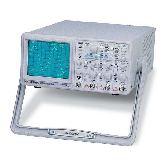
3A or 5A fuse. Larger conductors would normally require 13A types, depending on the connection method used. The GRS-6052A and GRS-6032A set a standard in performance and economy, Any moulded mains connector that requires removal /replacement must be each equips with two professional scopes in one. -
Page 4: Feature
GRS-6052A/6032A OSCILLOSCOPE GRS-6052A/6032A OSCILLOSCOPE USER MANUAL USER MANUAL The built-in RS-232C interface enables remote control operation and 1-2.Features signal processing via a PC. Additionally, the oscilloscope offers several other features: The X-Y mode is same as the real time mode. The X (horizontal) signal is... -
Page 5: Technical Specifications
Approx. 1MΩ±2% // approx. 25pF Vertical Modes CH1, CH2, DUAL(CHOP/ALT), ADD, CH2 INV. CHOP Frequency Approx. 250kHz. Dynamic Range GRS-6052A: 8DIV at 40MHz, 6DIV at 50MHZ (REAL TIME mode GRS-6032A: 8DIV at 20MHz, 6DIV at 30MHz only) ⎯ ⎯ ⎯... - Page 6 SYSTEM average (2~256). Sweep Magnification ×5, ×10, ×20 MAG Single shot: DC to 25MHz. Storage Bandwidth(- (REAL TIME GRS-6052A:20ns/DIV (10ns/DIV uncalibrated) Repetitive : DC to 50MHz (GRS-6052A) Maximum Sweep Time 3dB) GRS-6032A:50ns/DIV(10ns/DIV~40ns/DIV DC to 30MHz (GRS-6032A) (at MAG) uncalibrated. mode) ±5DIV.
-
Page 7: Precautions Before Operation
GRS-6052A/6032A OSCILLOSCOPE GRS-6052A/6032A OSCILLOSCOPE USER MANUAL USER MANUAL 3.PRECAUTIONS BEFORE OPERATION CH1/CH2 sensitivity, sweep time, trigger Panel Setting Display condition, digital storage function. Panel Setting Save & 3-1.Unpacking the Oscilloscope 10 sets Recall CURSOR The product has been fully inspected and tested before shipping from the Cursor Measurement Function: ΔV, ΔT, 1/ΔT. -
Page 8: 3-3.Environment
GRS-6052A/6032A OSCILLOSCOPE GRS-6052A/6032A OSCILLOSCOPE USER MANUAL USER MANUAL 4. PANEL INTRODUCTION 3-3.Environment After the instrument is switched on, all the important settings are displayed in the The normal ambient temperature range of this instrument is from 0° to 40°C readout. The LED’s located on the front panel assist operation and indicate (32°... -
Page 9: 4-1.Front Panel
LED indicates “ON” condition. (2) TRACE ROTATION The TRACE ROTATION is for aligning the horizontal trace in parallel with graticule lines. This potentiometer can be adjusted with a small screwdriver. Front panel of GRS-6052A ⎯ ⎯ ⎯... - Page 10 GRS-6052A/6032A OSCILLOSCOPE GRS-6052A/6032A OSCILLOSCOPE USER MANUAL USER MANUAL △V: Two horizontal cursors appear. The voltage between the two cursors is (3) INTEN—Control knob (REAL TIME Mode only) The control knob is used for adjusting the traces intensity in the real time calculated according to the setting of VOLTS/DIV, and displayed with △V on the upper side of the CRT.
- Page 11 GRS-6052A/6032A OSCILLOSCOPE GRS-6052A/6032A OSCILLOSCOPE USER MANUAL USER MANUAL △T on the upper side of the CRT. (10). SAVE—RECALL 1/△T: Two vertical cursors appear. The reciprocal of the time (frequency) The instrument contains 10 non-volatile memories, which can be used by the between the two cursors is calculated with 1/△T on the upper side of...
- Page 12 GRS-6052A/6032A OSCILLOSCOPE GRS-6052A/6032A OSCILLOSCOPE USER MANUAL USER MANUAL Vertical controls (15) ALT/CHOP The vertical controls select the displayed signals and control the amplitude In the REAL TIME mode, the pushbutton has two functions, which are characteristics. required and available only when both channels are active.
- Page 13 GRS-6052A/6032A OSCILLOSCOPE GRS-6052A/6032A OSCILLOSCOPE USER MANUAL USER MANUAL The deflection coefficients and additional information regarding the active (23) CH1-X—Input BNC socket channels are displayed in the readout. This BNC socket is the signal input for channel 1. In X-Y mode, signals at this input are used for the X deflection.
- Page 14 GRS-6052A/6032A OSCILLOSCOPE GRS-6052A/6032A OSCILLOSCOPE USER MANUAL USER MANUAL (25) H POSITION (Real Time mode only) (27) X-Y The control knob enables a horizontal position shift of the signals. In Pressing the pushbutton when using the instrument as an X-Y oscilloscope.
- Page 15 GRS-6052A/6032A OSCILLOSCOPE GRS-6052A/6032A OSCILLOSCOPE USER MANUAL USER MANUAL Trigger controls (31) SOURCE—Pushbutton The trigger controls determine the sweep start timing for both signals. Pressing the pushbutton to select the trigger signal source. The actual setting is indicated by the readout (“SOURCE”, slope, coupling).
- Page 16 GRS-6052A/6032A OSCILLOSCOPE GRS-6052A/6032A OSCILLOSCOPE USER MANUAL USER MANUAL (32) TV—Pushbutton for video sync signal selection (34) COUPLING— Separate the video sync signal from the composite waveform and direct it to Pressing the pushbutton to select the trigger coupling. The actual setting is the triggering circuit.
- Page 17 GRS-6052A/6032A OSCILLOSCOPE GRS-6052A/6032A OSCILLOSCOPE USER MANUAL USER MANUAL When the setting (voltage) value is out of the changing portion of the Storage Control observation waveform, the synchronization sweep stops. The Storage Control select the digital storage function. TRG LED The TRG LED is lit if the triggering conditions are met. Whether the LED flashes or is lit constantly depends on the frequency of the trigger signal.
- Page 18 GRS-6052A/6032A OSCILLOSCOPE GRS-6052A/6032A OSCILLOSCOPE USER MANUAL USER MANUAL (41) SINGLE BEEP ON/OFF Pressing the pushbutton to set the SINGLE mode and the “SINGLE” message When the “BEEP” is displayed, turning the VARIABLE control knob to set will be indicated in the readout.
-
Page 19: 4-2.Rear Panel
GRS-6052A/6032A OSCILLOSCOPE GRS-6052A/6032A OSCILLOSCOPE USER MANUAL USER MANUAL 4-2. Rear Panel (45)CH1 Output—BNC socket The rear panel provides input power and additional signal connections. This output may be used to connect to a frequency counter or other instrument. (46)Z-Axis Input—BNC socket Connect external signals to the Z-axis amplifier for intensity modulating the CRT display. -
Page 20: Operation Method
GRS-6052A/6032A OSCILLOSCOPE GRS-6052A/6032A OSCILLOSCOPE USER MANUAL USER MANUAL 5. OPERATION METHOD This section contains basic operation information and techniques that should be considered before proceeding any measurement. As for the location and function of instrument controls, connectors, and indicators, refer to the “Instruction of Front Panel and Rear Panel”... -
Page 21: 5-2.Connecting Input Signals
GRS-6052A/6032A OSCILLOSCOPE GRS-6052A/6032A OSCILLOSCOPE USER MANUAL USER MANUAL 5-2.Connecting Input Signals Grounding The most reliable signal measurements are made when the oscilloscope and the unit under test are connected by a common reference (ground lead) in addition to the signal lead or probe. The ground lead of the probe provides the best grounding method for signal interconnection and ensures the maximum amount of signal-lead shielding in the probe cable. -
Page 22: 5-3.Adjustment And Checks
GRS-6052A/6032A OSCILLOSCOPE GRS-6052A/6032A OSCILLOSCOPE USER MANUAL USER MANUAL 5-3.Adjustments and checks either probe does not need to be adjusted, proceed the “Function Check”. Trace Rotation Adjustment Normally, when the trace is in parallel with the center horizontal graticule line, there will be no need to adjust the TRACE ROTATION. If necessary, adjust the TRACE ROTATION to make the baseline trace parallel to the center horizontal graticule line by using a small straight-blade screwdriver or alignment tool. -
Page 23: 5-4.Function Check
GRS-6052A/6032A OSCILLOSCOPE GRS-6052A/6032A OSCILLOSCOPE USER MANUAL USER MANUAL 5-4.Function Check When you start to check the operation of your oscilloscope, proceed the 4. Set both CH1 and CH2 COUPLING to GND. following instruction: 5. Use the CH1 and CH2 POSITION controls to align both traces on the center 1. -
Page 24: 5-5.Basic Operation
GRS-6052A/6032A OSCILLOSCOPE GRS-6052A/6032A OSCILLOSCOPE USER MANUAL USER MANUAL 5-5.Basic Operation Displaying the sum or difference of CH1 and CH2 Displaying CH1 or CH2 To display the algebraic sum or difference of CH1 and CH2, proceed the To display the signal from a signal channel, pressing briefly the CH1 or CH2 following steps: pushbutton to set the oscilloscope to channel 1 or channel 2. - Page 25 GRS-6052A/6032A OSCILLOSCOPE GRS-6052A/6032A OSCILLOSCOPE USER MANUAL USER MANUAL Comparing Frequency and phase (X-Y Operation) Magnifying Waveform Events To compare the frequency and phase between two signals by using the X-Y Use the MAG pushbutton to view small portions of a waveform as which is too mode.
- Page 26 GRS-6052A/6032A OSCILLOSCOPE GRS-6052A/6032A OSCILLOSCOPE USER MANUAL USER MANUAL MAG-ALT Function Operating Hold off time Control (REAL TIME mode only) The input Signal is displayed by pressing MAG(magnify) and MAG-ALT(LED When the measured signal is a complex waveform with two or more repetition...
- Page 27 GRS-6052A/6032A OSCILLOSCOPE GRS-6052A/6032A OSCILLOSCOPE USER MANUAL USER MANUAL The VERT-MODE triggering is not possible when the signal is applied only to Observing the Synchronization of two Waveforms When two signals of the CH1 and CH2 have the same frequencies with an...
-
Page 28: 5-6.Digital Storage Functions
GRS-6052A/6032A OSCILLOSCOPE GRS-6052A/6032A OSCILLOSCOPE USER MANUAL USER MANUAL 5-6. Digital Storage Functions Triggering of Video signal In the work concerned with TV, complex signals and containing video signal, The operation procedure of the digital storage functions is described below. blanking pedestal signal, and synchronizing signal are often measured. - Page 29 GRS-6052A/6032A OSCILLOSCOPE GRS-6052A/6032A OSCILLOSCOPE USER MANUAL USER MANUAL Figure 5-16 ROLL mode Figure 5-17 The displayed waveform is rolled from right to left (0.2s/DIV to 100s/DIV). NOTE: The right end of each trace is the updating point of a new data. The Roll mode Aliasing: facilitates the measurement of a signal of approximately 100Hz or lower.
- Page 30 GRS-6052A/6032A OSCILLOSCOPE GRS-6052A/6032A OSCILLOSCOPE USER MANUAL USER MANUAL PRE-TRIGGER MENU Measure the waveform before the trigger point. The acquisition mode, the on-off settings of the waveform smoothing, the Although a conventional oscilloscope displays the trigger point only at the left...
- Page 31 GRS-6052A/6032A OSCILLOSCOPE GRS-6052A/6032A OSCILLOSCOPE USER MANUAL USER MANUAL SMPL(0.1s~1μs/div) Smoothing selection mode In normal sampling mode, the instrument generates a record point by When the “MENU 1: SMOOTH” is displayed at the top right of the CRT, saving the first sample during each acquisition interval.
- Page 32 GRS-6052A/6032A OSCILLOSCOPE GRS-6052A/6032A OSCILLOSCOPE USER MANUAL USER MANUAL waveform is magnified as is in the horizontal direction. RECALL reference In the case of LINEAR, the data is interpolated linearly, and the waveform When the “MENU5:RECALL” is displayed at the top right of the CRT, is displayed smoother than at DOT.
-
Page 33: 5-7.Measurement Application
GRS-6052A/6032A OSCILLOSCOPE GRS-6052A/6032A OSCILLOSCOPE USER MANUAL USER MANUAL 5-7.Measurement Application Figure 5-19: Cursor Measurement (a).Typical △V (Voltage difference) for The oscilloscope has a cursor measurement system for making accurate, direct- AC voltage. readout voltage, time and frequency measurements. The measurements When both CH1 and CH2 are turned on, the measurement value of CH1(△V1). - Page 34 1. No connection Figure 5-21. DB9 to DB9 wiring 2. Receive Data (RxD) (input) When the GRS-6052A/6032A is set up with a RS232 interface, please check the 3. Transmit Data (TxD) (output) following points: 4. No connection Do not connect the output line of one DTE device to the output line of the other.
- Page 35 A personal computer with a COM port is the essential facility in order to operate the GW,GRS60X2A,V.1.10 instruction via RS232 interface. The connections between GRS-6052A/6032A and computer are as follows: If you do not receive a proper response from the GRS-60X2A, please check if the Connect one end of a RS232 cable to the computer.
- Page 36 GRS-6052A/6032A OSCILLOSCOPE GRS-6052A/6032A OSCILLOSCOPE USER MANUAL USER MANUAL Here are some valid examples remote control commands (not including message 5-8.2. RS-232 Remote Control terminator): Command Syntax V 1 = 0 1 0 A H 4 = 0 0 1 All commands syntax is ASCII format. If you want to transfer any of the instructions to an instrument, there are five basic elements must be included.
- Page 37 GRS-6052A/6032A OSCILLOSCOPE GRS-6052A/6032A OSCILLOSCOPE USER MANUAL USER MANUAL Message Terminator and Message Separator If instrument receives W0?-W9?. It will return 3 bytes waveform information, 1000 As there is no signal of end message on RS232 bus, therefore use LF (Line Feed, 0×...
- Page 38 GRS-6052A/6032A OSCILLOSCOPE GRS-6052A/6032A OSCILLOSCOPE USER MANUAL USER MANUAL Buffer Size Command List The command receive buffer of instrument is 128 bytes. The return message buffer of instrument is 1024 bytes. Note: Every command must add 1 byte message terminator of LF (0x0A).
- Page 39 GRS-6052A/6032A OSCILLOSCOPE GRS-6052A/6032A OSCILLOSCOPE USER MANUAL USER MANUAL T5=<Parameters (3bytes)> Trigger Slope V8=<Parameters (3bytes)> ALT/CHOP WA? WB? WC? WD? Dump Waveform H1=<Parameters (3bytes)> W [0-9] ? Horizontal Scale M1=<Parameters (3bytes)> Smooth H2=<Parameters (3bytes)><Target (1byte)> Pre-trigger Position M2=<Parameters (3bytes)> Average H3=<Parameters (3bytes)>...
- Page 40 GRS-6052A/6032A OSCILLOSCOPE GRS-6052A/6032A OSCILLOSCOPE USER MANUAL USER MANUAL Details of Command Reference *RST Each command in this chapter will give a brief description. The examples of each command will be provided and what query form might return. Note: Every command must add 1 byte message terminator of LF (0x0A).
- Page 41 GRS-6052A/6032A OSCILLOSCOPE GRS-6052A/6032A OSCILLOSCOPE USER MANUAL USER MANUAL Sets or queries the channel’s display. Input Coupling Syntax V3=001A Parameters (3Bytes) Target V3?B Arguments Target Parameters: Sets or queries the input coupling states. 000→Disable channel display 001→Enable channel display Syntax Target: V2=001B A→Channel 1...
- Page 42 GRS-6052A/6032A OSCILLOSCOPE GRS-6052A/6032A OSCILLOSCOPE USER MANUAL USER MANUAL Target: A→Channel 1 B→Channel 2 Sets or queries the invert function. Syntax V-VAR V6=001 Parameters (3Bytes) Target Arguments Parameters Target 000→Disable invert function Sets or queries the vertical VAR function of the specified channel.
- Page 43 GRS-6052A/6032A OSCILLOSCOPE GRS-6052A/6032A OSCILLOSCOPE USER MANUAL USER MANUAL ALT/CHOP Arguments Parameters (3Bytes) Parameters: 001→100s/DIV 002→50s/DIV 003→20s/DIV 004→10s/DIV 005→5s/DIV 006→2s/DIV Sets or queries the ALT/CHOP mode. 007→1s/DIV 008→.5s/DIV 009→.2s/DIV Syntax 010→.1s/DIV 011→50ms/DIV 012→20ms/DIV V8=001 013→10ms/DIV 014→5ms/DIV 015→2ms/DIV 016→1ms/DIV 017→.5ms/DIV 018→.2ms/DIV Arguments 019→.1ms/DIV...
- Page 44 GRS-6052A/6032A OSCILLOSCOPE GRS-6052A/6032A OSCILLOSCOPE USER MANUAL USER MANUAL Arguments XY Mode Parameters: Parameters (3Bytes) If Target=A, Parameter range→0 (0 DIV) to 500 (-10DIV) If Target=B, Parameter range→0 (0DIV) to 200 (4 DIV) Target: Sets or queries the XY mode A→Pre B→Post...
- Page 45 GRS-6052A/6032A OSCILLOSCOPE GRS-6052A/6032A OSCILLOSCOPE USER MANUAL USER MANUAL Trigger Commands Arguments Parameters: 000→MAG Disable 001→X5 Trigger Mode 002→X10 003→X20 Parameters (3Bytes) MAG-ALT Parameters (3Bytes) Sets or queries trigger mode Syntax T1=001 Sets or queries the MAG-ALT mode Syntax Arguments H6=001 Parameters: 000→Auto trigger mode...
- Page 46 GRS-6052A/6032A OSCILLOSCOPE GRS-6052A/6032A OSCILLOSCOPE USER MANUAL USER MANUAL Arguments Parameters: Sets or queries TV trigger mode 000→VERT 001→Channel 1 Syntax 002→Channel 2 003→Line T4=001 004→External Arguments Trigger Coupling Parameters: 000→Disable TV trigger. Parameters (3Bytes) 001→Vertical TV trigger mode 002→Horizontal TV trigger mode...
- Page 47 GRS-6052A/6032A OSCILLOSCOPE GRS-6052A/6032A OSCILLOSCOPE USER MANUAL USER MANUAL Waveform Data Commands Menu Commands Dump Waveform Smooth Parameters (3Bytes) Dump channel 1 waveform data Sets or queries the waveform smooth function Dump channel 2 waveform data Syntax M1=001 Dump 2 recalled waveform data...
- Page 48 GRS-6052A/6032A OSCILLOSCOPE GRS-6052A/6032A OSCILLOSCOPE USER MANUAL USER MANUAL Arguments Sets or queries the Acquisition Mode Parameters: Syntax 000→Disable average function M4=001 001→Average number is 2 002→Average number is 4 003→Average number is 8 004→Average number is 16 Arguments 005→Average number is 32 006→Average number is 64...
- Page 49 GRS-6052A/6032A OSCILLOSCOPE GRS-6052A/6032A OSCILLOSCOPE USER MANUAL USER MANUAL Arguments Syntax Parameters: O3=030 001→Real-Time mode 000→Storage mode Run/Stop: Arguments Parameters: Parameters (3Bytes) 000→Disable text display 001 (Min) to 060 (Max)→Text intensity Illumine intensity Sets or queries the waveform Run/Stop function Parameters (3Bytes)
-
Page 50: Maintenance
GRS-6052A/6032A OSCILLOSCOPE GRS-6052A/6032A OSCILLOSCOPE USER MANUAL USER MANUAL 6. MAINTENENCE 6-3. Cleaning To clean the oscilloscope, use a soft cloth dampened in a solution of mild The instructions below are executed by qualified personnel only. To avoid detergent and water. Do not spray cleaner directly onto the oscilloscope electrical shock, do not perform any servicing other than the operating instructions because it may leak into the cabinet and cause damage. -
Page 51: Block Diagram
GRS-6052A/6032A OSCILLOSCOPE GRS-6052A/6032A OSCILLOSCOPE USER MANUAL USER MANUAL 7.Block Diagram ⎯ ⎯ ⎯ ⎯...
Need help?
Do you have a question about the GRS-6032A and is the answer not in the manual?
Questions and answers