
Related Manuals for GW Instek GLC-9000


Summary of Contents for GW Instek GLC-9000
- Page 1 LEAKAGE CURRENT TESTER GLC-9000 USER MANUAL GWINSTEK PART NO.:82LC-90000EB1 ISO-9001 CERTIFIED MANUFACTURER GlobalTestSupply www. .com Find Quality Products Online at: sales@GlobalTestSupply.com...
- Page 2 This manual contains proprietary information, which is protected by copyright. All rights are reserved. No part of this manual may be photocopied, reproduced or translated to another language without prior written consent of Good Will Corporation. The information in this manual was correct at the time of printing. However, Good Will continues to improve its products and therefore reserves the right to change the specifications, equipment, and maintenance procedures at any time without notice.
-
Page 3: Table Of Contents
Table of Contents Table of Contents SAFETY INSTRUCTIONS ........7 Safety Symbols ............... 7 Safety Guidelines ..............8 Power cord for the United Kingdom ........11 OVERVIEW............. 13 Introduction ..............13 Leakage Current Modes ............14 Measurement Principles ............15 Measuring Devices ............... - Page 4 GLC-9000 User Manual Enclosure and Line Leakage Current ........50 Patient Auxiliary Current ............ 52 Patient Leakage Current I ..........53 Patient Leakage Current II ..........55 Patient Leakage Current III ..........56 MEASUREMENT ..........59 Interface ................59 Selecting the Safety Class/ Grounding Class ..... 63 Selecting a Measuring Network .........
- Page 5 Table of Contents Voltage Measurement ............101 Initialize Menu ..............104 Version and Serial Number ..........108 EUT Outlet Settings ............108 REMOTE CONTROL ........111 Remote Control Settings ..........111 Remote Connection ............112 Command Syntax ............. 114 Command List ..............118 Measurement Network Commands ........
- Page 6 GLC-9000 User Manual Status Byte Register............156 Standard Event Register ..........158 Status Byte Register Command ........159 Standard Event Register Commands ........ 160 Other Status Register Commands ........161 Errors ................162 Command Errors ............... 162 Execution Errors ..............164 Device Specific Errors ............
-
Page 7: Safety Instructions
SAFETY INSTRUCTIONS AFETY INSTRUCTIONS This chapter contains important safety instructions that you must follow when operating or storing a GLC-9000 series current leakage tester. Following these instructions will ensure your safety and keep the instrument in the best possible condition. -
Page 8: Safety Guidelines
are qualified as service personnel. (Measurement categories) EN 61010-1:2001 specifies the measurement categories and their requirements as follows. the GLC-9000 falls under category I Measurement category IV is for measurement performed at the source of low-voltage installation. ... - Page 9 Temperature: 0°C to 40°C (Pollution Degree) EN 61010-1:2001 specifies the pollution degrees and their requirements as follows. The GLC-9000 falls under degree Pollution refers to “addition of foreign matter, solid, liquid, or gaseous (ionized gases), that may produce a reduction of dielectric strength or surface resistivity”.
- Page 10 GLC-9000 User Manual Do not dispose this instrument as unsorted Disposal municipal waste. Please use a separate collection facility or contact the supplier from which this instrument was purchased. Please make sure discarded electrical waste is properly recycled to reduce environmental impact.
-
Page 11: Power Cord For The United Kingdom
SAFETY INSTRUCTIONS Power cord for the United Kingdom When using a GLC-9000 series current leakage tester in the United Kingdom, make sure the power cord meets the following safety instructions. NOTE: This lead/appliance must only be wired by competent persons... -
Page 12: Overview
OVERVIEW VERVIEW This chapter describes the GLC-9000 in a nutshell, including the main features, front and rear panel description, and the power up sequence. Introduction Many electrical products must undergo electrical Overview safety testing to ensure their safety. These tests include insulation resistance, withstand voltage, ground continuity and leakage current tests. -
Page 13: Leakage Current Modes
GLC-9000 User Manual Leakage Current Modes Refers to the current that flows through a Earth protective grounding wire to earth. (General Leakage Current Electrical, Medical Equipment) Refers to the current that flows through a human Enclosure Leakage body in contact with a device enclosure. (General... -
Page 14: Measurement Principles
OVERVIEW Refers to the current that flows through a human Patient Leakage body that is directly connected to a device that Current III malfunctions. (Medical Equipment) Refers to the current that flows through a human Patient Auxiliary and a device during normal operation. This is not Current intended to be perceptive. -
Page 15: Measuring Devices
GLC-9000 User Manual Single Fault conditions include the following: Earth disconnected (excluding earth leakage current tests). Disconnected neutral power line. External equipment failure. (Patient leakage current II, Patient Leakage Current III). Polarity of the power supply can also be switched to measure the leakage current under test. - Page 16 OVERVIEW circuits are resistor-capacitor (RC) circuits. The GLC- 9000 supports 9 different measuring devices. IEC60990s MD-A MD-B MD-C JIS Standards MD-I General Purpose MD-E MD-H UL Standards MD-D MD-G Medical MD-F MD-F (without RC filter) Networks GlobalTestSupply www. .com Find Quality Products Online at: sales@GlobalTestSupply.com...
- Page 17 GLC-9000 User Manual When conducting leakage current tests, please note Note the following: Under normal operating conditions, leakage current is measured when an electrical device under test is properly insulated with earth. If the device is not properly insulated, the leakage current that is conducted through the measurement network may be invalid.
-
Page 18: Key Features
OVERVIEW Key Features The GLC-9000 has nine measurement networks International (Measuring Devices: MD) supporting GB/12113, Standards and Regulations IEC/UL and other international standards for electrical products: (1) MD-A:IEC60990 (2) MD-B:IEC60990 (3) MD-C:IEC60990 (4) MD-D:UL (5) MD-E(1kΩ):-general application (6) MD-F: Medical (7) MD-G:UL (8) MD-H:(2kΩ)-general application... - Page 19 GLC-9000 User Manual Automatic/Manual ranges: Measurement Range DC/AC/AC+DC:50uA/500uA/5mA/25mA (Range:4uA~25mA) AC Peak:500uA/1mA/10mA/75mA (Range:40uA~75mA) Auto/Manual/Programmable Operation Single fault conditions and power supply polarity switch Measurement/Delay time settings Maximum / minimum hold PASS/FAIL(Upper, Lower) Judgement (limits) save and recall setup and measurement results ...
- Page 20 OVERVIEW 30 sets of memory for user defined test Memory conditions 50 sets of standard test conditions. (e.g., IEC60990) 100 sets of measurements can be saved/recalled Remote Interface There are a variety of remote control interfaces including: RS-232, USB (Host/Device), GPIB and the EXT I/O connector.
-
Page 21: Basic Theory
GLC-9000 User Manual Basic Theory GLC-9000 consists of the following blocks as Overview illustrated in the figure below. Tester and EUT power supply MD (Measuring Device) circuit network Current detection Signal Process CPU/Digital control ... - Page 22 OVERVIEW This switching matrix controls relays to alter the EUT Power EUT power to simulate a number of different test Switching conditions, such as earth open or reverse polarity, etc. Different MD networks represent different MD Network equivalent circuits of a human body. They are chosen according to different regulations.
-
Page 23: Leakage Current Modes
GLC-9000 User Manual Leakage Current Modes As illustrated below, the leakage current generated Definition with a high voltage in an electrical appliance requires measurement under normal EUT (Equipment Under Test) conditions and under single fault conditions. Leakage current can be... - Page 24 OVERVIEW Leakage current can be dangerous and produce shocks over a certain limit. Enclosure and Earth leakage current Enclosure and Earth Leakage Current During normal conditions, an operator or a patient Description is expected to touch the enclosure of an instrument (except for applied parts).
- Page 25 GLC-9000 User Manual Enclosure and Enclosure Leakage Current Enclosure and Enclosure Leakage Current Under normal or single fault conditions, the Description leakage current that flows through a human body from any 2 isolated parts of the enclosure. Patient Leakage Current I...
- Page 26 OVERVIEW Patient Leakage Current II Faulty Equipment Applied Part Patient Leakage Current 2 Patient leakage current II refers to the current that Description flows from an applied part through a human body to earth. For the test it is assumed that an external I/O device that is connected to the signal input of the EUT malfunctions with an output of 110% of the rated voltage.
- Page 27 GLC-9000 User Manual Patient Leakage Faulty Equipment Current III Patient Leakage Current 3 Applied Part Patient Leakage Current III is the leakage current Description that flows from a malfunctioning applied part, through a person, and through a Type F applied part.
-
Page 28: Leakage Current Modes
OVERVIEW Leakage Current Modes Single Normal Type Fault Description Notes Condition Fault Earth Leakage Class 1 Power line disconnected. only Current Enclosure to 1. Power line Earth leakage Class 1 disconnected. only* current 2. Disconnected earth Enclosure to protection*. Enclosure 3.110% of the rated power leakage current supply voltage applied... -
Page 29: Measurement Flow Chart
GLC-9000 User Manual Measurement Flow Chart Start Reference Page Getting Started Check the fuse and power Getting Started Power up Selecting the Safety Class Select a class type Select a measurement Network Selecting a Meas. Network Select the Upper and Lower Limits Selecting Meas. -
Page 30: Front Panel
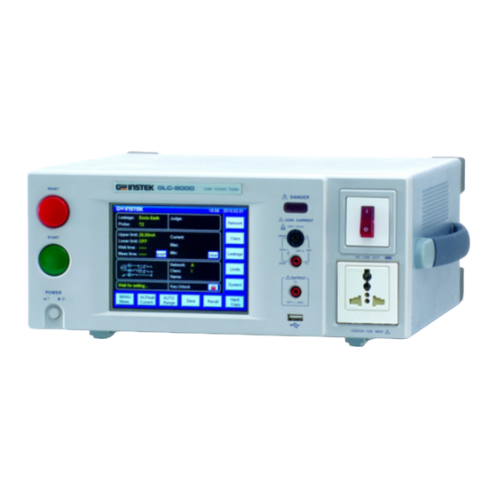
OVERVIEW Front Panel GLC-9000 g DANGER LEAKAGE CURRENT 250V T32mA 25mA 250V CAT II AC LINE OUT 25mA GLC-9000 OUTPUT CAT II 250V 1500 VA/10A MAX Item Description The power switch turns the power 1. POWER on or off. - Page 31 GLC-9000 User Manual GLC-9000 The warning indicator lights up 5. Warning when high voltages are produced Indicator from terminals T1, T2 or T3. The warning indicator will flash when in standby mode. Measuring Terminals T1 and T2 are 6. Measuring...
-
Page 32: Rear Panel
OVERVIEW Rear Panel ITEM Description EUT AC inlet. AC voltage range: 1. EUT AC IN 85V~ 250V AC (Max. 264V AC) ... - Page 33 GLC-9000 User Manual The power socket accepts AC 6. Power Socket/ mains power for the GLC-9000. Fuse socket. Power: 100V/120/220/ 230V AC ...
-
Page 34: Touch Screen Basics
OVERVIEW Touch Screen Basics Do not use any sharp objects or excessive pressure on the touch screen display, doing so may damage Caution the display. The LCD touch panel is used to configure system Description and measurement settings. Touching an on-screen icon mimics the action of pressing a button on traditional machines. - Page 35 GLC-9000 User Manual Any keys or icons that are dimmed indicate currently unavailable menus, icons or areas. This is shown in the screen capture below. GlobalTestSupply www. .com Find Quality Products Online at: sales@GlobalTestSupply.com...
-
Page 36: Getting Started
GETTING STARTED ETTING STARTED This chapter describes the GLC-9000 in a nutshell, including the main features, front and rear panel descriptions, and the power up sequence. Preparation Before power is turned on, Voltage Line ensure the line voltage is Selection ... -
Page 37: Power And Probe Connection
GLC-9000 User Manual Note the position of the live EUT Line In Warning and neutral line inputs for the EUT line in and the EUT AC EUT Power Input power block. Failing to connect wiring. the EUT input properly will affect the measurement accuracy. - Page 38 GETTING STARTED 2. Insert the power cord as shown on the right into the EUT AC Line In. The arrow above shows the EUT AC line in socket, located on the left-hand side of the rear panel. If network B (MD B) is selected an isolation Caution transformer that outputs 110% of the rated voltage specified for the EUT is required.
- Page 39 GLC-9000 User Manual Warning: To avoid the risk of electric shock, do not touch the tips of the test leads when operating. 1. The foil probe is used to measure the surface Foil Probe leakage current (touch current) of the EUT.
-
Page 40: Power Up
1. Turn on the power switch. Ensure the EUT Steps power switch is off. 2. The GLC-9000 will load the last panel setting before the last shut down. 3. Wait for the machine to warm up for 30 minutes before operating. -
Page 41: Shut Down
GLC-9000 User Manual Shut Down Before shutdown, ensure the EUT is shut down properly. As illustrated below, power off the circuit breaker before turning off the equipment. GLC-9000 EUT Power Down Ensure the circuit breaker is GLC-9000 turned off. -
Page 42: Operation
OPERATION PERATION Measurement Terminals When a measurement network is selected, different measuring terminals are required for each test and equipment class. The tables below list which terminals are used for with which network/test. Non-medical Network (General Electrical Appliance) MD-A, B, C, D, E, G, H, I CLASS I CLASS II Internal Power Supply... -
Page 43: Medical Equipment
Patient leakage current III *Type F = Type BF and Type CF. Earth Leakage Current N/A. Network 1. Connect the EUT power cord to the GLC-9000 Connection as shown in the diagram below. Confirm all settings including MD, leakage current Measurement... - Page 44 OPERATION Panel Operation 1. Turn on the circuit breaker. GLC-9000 Connect the EUT power GLC-9000 terminal. 2. Press the START button to start measurements. GLC-9000 3. Press the reset button to stop measurement. Turn the circuit breaker off before removing the EUT.
-
Page 45: Enclosure Leakage Current
GLC-9000 User Manual Enclosure Leakage Current Non medical network / Medical network Network As illustrated, ensure that the power source and Connection test leads are properly connected. 1. Connect the test lead to terminal T2. Non-Medical Network 2. Position the test lead on an ungrounded section... - Page 46 Confirm all settings including MD, leakage current Measurement mode, measurement time, upper and lower limits, Setup and other parameters. Panel Operation 3. Turn on the circuit breaker. GLC-9000 Connect the EUT to the GLC-9000 power socket. 4. Press the START button to start measurements.
-
Page 47: Enclosure To Enclosure Leakage Current
GLC-9000 User Manual Enclosure to Enclosure Leakage Current Non medical network / Medical network Network As illustrated, ensure that the power source and Connection test leads are properly connected. 1. Connect the tests lead to terminals T1& T2. Non-Medical network 2. - Page 48 Confirm all settings including MD, leakage current Measurement Setup mode, measurement time, upper and lower limits, and other parameters. Panel Operation 1. Turn on the circuit breaker. GLC-9000 Connect the EUT to the GLC-9000 power socket. 2. Press the START button to start measurements.
-
Page 49: Enclosure And Line Leakage Current
GLC-9000 User Manual Enclosure and Line Leakage Current Non medical network / Medical network Network As illustrated below, ensure that the power source Connection and test leads are properly connected. 1. Connect the test lead to T2 terminal. Position Non Medical... - Page 50 OPERATION GLC-9000 4. Press the reset button to stop measurement. Turn the circuit breaker off before removing the EUT. Warning Ensure the power consumption of the EUT doesn’t exceed the rated power limits. Note This test is equipped with ground (earth) fault detection.
-
Page 51: Patient Auxiliary Current
GLC-9000 User Manual Patient Auxiliary Current Medical network Network As illustrated below, ensure that the power source Connection and test leads are properly connected. Medical Network 1. Connect the test leads to the T1 and T2 terminals. 2. Position the test leads to the applied part of the EUT. -
Page 52: Patient Leakage Current I
OPERATION GLC-9000 3. Press the reset button to stop measurement. Turn the circuit breaker off before removing the EUT. Warning Ensure the power consumption of the EUT doesn’t exceed the rated power limits. Patient Leakage Current I Medical network, (MD-F) for the applied part. - Page 53 GLC-9000 User Manual 1. Position the T2 test lead to the applied part of Class I/Class II the EUT. Class I and Class II Confirm all settings including MD, leakage current Measurement mode, measurement time, upper and lower limits, Setup and other parameters.
-
Page 54: Patient Leakage Current Ii
Confirm all settings including MD, leakage current Measurement Setup mode, measurement time, upper and lower limits, and other parameters. Panel Operation 3. Turn on the circuit breaker. GLC-9000 Connect the EUT to the power socket. GlobalTestSupply www. .com Find Quality Products Online at: sales@GlobalTestSupply.com... -
Page 55: Patient Leakage Current Iii
GLC-9000 GLC-9000 User Manual 4. Press the START button to start measurements. GLC-9000 5. Press the reset button to stop measurement. Turn the circuit breaker off before removing the EUT. Warning Ensure the power consumption of the EUT doesn’t exceed the rated power limits. - Page 56 Confirm all settings including MD, leakage current Measurement Setup mode, measurement time, upper and lower limits, and other parameters. Panel Operation 2. Turn on the circuit breaker. GLC-9000 Connect the EUT to the GLC-9000 power socket. 3. Press the START button to start measurements.
-
Page 57: Measurement
MEASUREMENT EASUREMENT Interface Remote control Time Network Set Limits Operation keys Power State Status Operation keys Main Display Displays the current measuring Network Leakage network types (general electrical equipment and medical networks): Earth leakage current Enclosure to earth leakage current ... - Page 58 GLC-9000 User Manual Patient leakage current I Patient leakage current II Patient leakage current III Shows the probe terminal used for Probe the current measuring network. See page 43 for details. Shows the test result judgment. Judge: Displays the upper test limit.
- Page 59 MEASUREMENT Occurs when the Meas key is pressed Ready after Network, Class or Leakage is chosen. Press the START button whilst in Testing Ready mode to enter Testing mode. The RESET option will be displayed when in Testing mode. Indicates that the touch panel is currently unlocked.
- Page 60 GLC-9000 User Manual Leakage Set leakage Leakage Limit current mode current limits selection Access the Sets the AUTO System system measurement Meas parameters mode Leakage Leakage current AC+DC AUTO current type range selection Current Range selection Save a screen Save settings.
-
Page 61: Selecting The Safety Class/ Grounding Class
MEASUREMENT Selecting the Safety Class/ Grounding Class 1. Press the Class button. Three Operation Class options appear in the Class setup panel. 2. To select a class, press one of the Class setup keys. Range Non Medical Class I, Class II, Int power Medical MD-F Class I, Class II, Int power, Type B, Type BF, Type CF 3. -
Page 62: Selecting A Measuring Network
GLC-9000 User Manual Selecting a Measuring Network 1. Press the Network key. Ten Operation Network network choices will appear in the Network Choice panel. 2. To choose a measuring network, press one of the network keys. Range Network A, B, C, D, E(1k), F, G, H(2k), I, J 3. - Page 63 MEASUREMENT 4. Press the R.C. Details key for R.C. details on each of the resistor Details capacitor networks. 5. Press Return to cancel Return selecting a measuring network and to return to the main screen. When the 1k pure resistance filter for Network F is Note selected, F(1k) is reflected on both the Main Display and in the panel settings, as shown below...
- Page 64 GLC-9000 User Manual Figure B. GlobalTestSupply www. .com Find Quality Products Online at: sales@GlobalTestSupply.com...
-
Page 65: Selecting A Measurement Mode
MEASUREMENT Selecting a Measurement Mode 1. Press the Leakage key to enter Operation Leakage the Leakage Current screen. 2. To choose a measurement mode, press one of the measurement mode keys. Range Non Medical Earth-Leak, Enclo-Earth, Enclo- Enclo, Enclo-Line Medical MD-F Earth-Leak, Enclo-Earth, Enclo- Enclo, Enclo-Line, Patient I, Patient II, Patient III, Patient aux, 3. -
Page 66: Selecting Measurement Parameters
GLC-9000 User Manual Selecting Measurement Parameters Before measurement parameters can be set, the network model, grounding class and measurement mode need to be configured. Setting the Limits 1. To set the Upper and lower Operation Limit limits, press the Limit key to enter the Current limit setup. -
Page 67: Auto/Manual Measurement Functions
MEASUREMENT 5. Press Return to go back to the Return previous menu. The lower current limit cannot be set for less than Note 4mA. Auto/Manual Measurement Functions The Meas key is used to configure either manual or Background automatic measurements. 1. - Page 68 GLC-9000 User Manual 1. Choose a Polarity. Manual Mode Range Non-Medical Live, Neutral (MD-B) Medical Normal, Reverse 2. Choose T3-Out. Range Medical (MD- 110%N, 110%R* Other 3. Choose the line Status. Range Non-Medical Normal, E-open, N-open Medical * 110% voltage application. N= normal,...
- Page 69 MEASUREMENT 4. Press Return to exit to the Return previous menu. Auto Mode 1. Choose Meas Item. Meas Item 2. Select Polarity and line Status parameters. Range Polarity Normal, Reverse T3-Out 110%N (100% voltage, normal connection, 110%R (110% voltage, reverse polarity) Status Normal, E-open, N-open Wait Time...
-
Page 70: Setting Leakage Current Type
GLC-9000 User Manual Meas Time MeasTime 5. Choose 6. Use the arrow keys and keys to set the delay time. 3 seconds 7. Press Return to exit from the Return Auto Meas menu. Setting Leakage current type 1. To set the leakage current Operation type, press the Current key. -
Page 71: Setting The Range
MEASUREMENT Setting the Range 1. To set the range, press the Operation AUTO Range key. Range 2. To set the range to automatic, AUTO Auto press 3. To set the hold range, press HOLD followed by a range. HOLD 500uA 500uA Range DC, AC,... - Page 72 GLC-9000 User Manual The leakage current range depends on the measuring Note network used. The table below shows the maximum and minimum values of each range for each network type. MD A~F,I AC, DC, Range 25.00mA 5.000mA 500.0uA 50.00uA AC+DC Maximum 25.00mA...
-
Page 73: Saving Measurement Results
MEASUREMENT Saving Measurement Results When a measurement has completed, all results Background will be displayed on the screen, as shown below. There are a number of options. Operation 1. Use the Up and Down arrow keys to scroll through the results. - Page 74 GLC-9000 User Manual Enter key pad Enter number 5. Press Return to return to the Return previous menu. GlobalTestSupply www. .com Find Quality Products Online at: sales@GlobalTestSupply.com...
-
Page 75: Save/Recall Features
SAVE/RECALL FEATURES AVE/RECALL FEATURES Save Settings The GLC-9000 can save panel settings into internal Background memory. The Panel settings save the following information: Measuring network Class Measurement Mode Upper and Lower Limits Measurement Settings (Polarity, Power line ... - Page 76 GLC-9000 User Manual 2. Use the up and down arrows to scroll each page of files. 3. Choose a save file to bring No.01 up the save file options. 4. To create or name the file, Rename press Rename. GlobalTestSupply www.
- Page 77 SAVE/RECALL FEATURES 5. Use the on-screen keyboard to enter a file name. Confirm TEST Back space Enter key pad Enter number 6. Press Yes to save the file. 7. Press No to cancel saving a file and return to the previous screen.
-
Page 78: Recall Panel Settings Or Data
GLC-9000 User Manual Recall Panel Settings or Data The Recall menu is divided into Recall Panel Background (settings) and Recall Data. Recall Panel will recall the panel settings, whilst Recall Data will recall the results data. There a total of 80 panel settings. - Page 79 SAVE/RECALL FEATURES 1. Use the up and down Recall Panel arrows to scroll through each page of saved files. 2. To recall a panel setting, No.01 choose a file to recall. The file’s panel settings will be displayed on the screen. GlobalTestSupply www.
- Page 80 GLC-9000 User Manual 3. Press Yes to recall the settings. The settings will be displayed on the main display. 4. Press No to cancel recalling the settings and return to the previous screen. 1. To recall data, press the Recall...
- Page 81 SAVE/RECALL FEATURES 4. To delete highlighted data, Delete data use the Delete Data key. 5. Press Return to return to the Return previous menu. GlobalTestSupply www. .com Find Quality Products Online at: sales@GlobalTestSupply.com...
-
Page 82: Usb Storage
Connection and Navigation The USB port is used to copy files (panel settings, Background measurement results, screen images) and for performing firmware updates. The GLC-9000 recognizes*.CSV *.BMPand *.BIN File Format file formats. Only 8.3 length filenames are supported. File name 1. - Page 83 GLC-9000 User Manual The flash drive will be automatically detected after insertion. Once detected, the USB icon will appear on the status panel. 1. To access the System setup Operation System menu, press the System key. 2. Press USBStorage from the USB Storage System setup menu.
-
Page 84: Copy Files To Usb
USB Storage 1. To navigate the USB file File Navigation system, use the Up and Down arrow keys. 2. Press Open to open a Open highlighted directory. 3. Press Return to return to the Return Return system menu. Copy files to USB Panel settings and data can be copied to USB Background storage. -
Page 85: Firmware Update
Firmware Update The firmware can be updated via the USB drive. Background For the latest firmware, please see your local distributor or contact GW Instek at All firmware updates use a *.bin file format. File Format 1. Highlight a firmware file Operation (*.bin) in the USB Storage... -
Page 86: Save A Screen Image
USB Storage Update 2. Press the Update key. GLC-9000 Wait while the system updates. Save a Screen Image Screen shots of the main display can be captured Background via the Hardcopy key. Each screen shot is saved as a bitmap (*.BMP) file in a directory named GLC9000. - Page 87 GLC-9000 User Manual If a USB disk has not been inserted, you will be Note prompted to insert a USB flash disk after the Hardcopy key is pressed. GlobalTestSupply www. .com Find Quality Products Online at: sales@GlobalTestSupply.com...
-
Page 88: System Settings
SYSTEM SETTINGS YSTEM SETTINGS The System key is used to access the System setup Background menu. The system setup menu can then be used to access a number of different system menus. Panel Operation 1. To access the System setup System menu, press the System key. -
Page 89: Alarm/Tone Settings
GLC-9000 User Manual Alarm/Tone Settings The Beep menu is used to set alarm tones for Background different events. Panel Operation 1. Press Beep from the System Beep setup menu. Setting an event to ON will allow an alarm tone to be heard when that event occurs. -
Page 90: Date And Time Settings
SYSTEM SETTINGS Date and Time Settings The Date and Time menu is used to set the time and Background date. Panel Operation 1. To access the Date and Time Date/Time menu press the Date&Time key. 2. Use the up and down arrow keys to set the date and time. -
Page 91: Language Selection
GLC-9000 User Manual Language Selection Use the Language Selection menu to select the Background language used for the user interface. Panel Operation 1. To access the Language Language Selection menu, press the Language key from the System setup menu. 2. Choose a language. -
Page 92: System Self Test
SYSTEM SETTINGS System Self Test The system self-test function allows the system Background functions to be checked automatically. Panel Operation 1. To access the Self-test menu, Self-test press the Self-test key from the System setup menu. 2. To perform a self test, choose any of the soft test functions (LED, LCD, RAM, Sound). -
Page 93: Lcd/Touch Screen Settings
GLC-9000 User Manual LCD/Touch Screen Settings The LCD & Touch Panel menu adjusts the LCD Background backlight wait time and calibrates the touch panel. Panel Operation 1. To access the LCD & Touch LCD/TP Panel menu, press the LCD/TP key from the System setup menu. - Page 94 SYSTEM SETTINGS 3. Press Return to return to the Return System setup menu. 1. Press Calibration to enter the LCD Calibration Calibration calibration screen. 2. Press each of the X’s in the center to calibrate the LCD. 3. Press Cancel to cancel the Cancel calibration.
-
Page 95: Eut Voltage And Current Check
GLC-9000 User Manual EUT Voltage and Current Check The EUT voltage and current check tests voltage, Background current and power consumption. Panel Operation 1. To access the EUT voltage & V/A Check current check menu, press the V/A Check key from the System setup menu. -
Page 96: Interface
SYSTEM SETTINGS Interface The Interface menu is used to select the remote Background control interface and interface settings. After a connection has been established, an interface icon will be shown in the LCD display. Panel Operation 1. To access the Interface menu, Interface press the Interface key from the System setup menu. - Page 97 GLC-9000 User Manual 3. To set the interface to USB, press USB. 4. Click the arrow and select a baud rate from the drop down list. Range 4800~115200 baud, 8 bit data, no parity check, 1 stop bit. 1. To set the interface to GPIB,...
-
Page 98: Voltage Measurement
Panel Operation 1. Press the Meter key to access Meter the Voltage Meter (T1/T2) menu. 1. Choose the current type. Meter Mode AC+DC GLC-9000 AC Peak 2. Press the start button to begin measurements. Range AC, DC, AC+DC, AC Peak GlobalTestSupply www. - Page 99 GLC-9000 User Manual Measurements are shown in the center of the screen. 1. To set the safety extra low SELV SELV voltage, press the SELV key. When the voltage exceeds the safety extra low voltage (SELV), the warning indicator will become illuminated and an alarm will sound.
- Page 100 SYSTEM SETTINGS 2. To set the SELV use the number pad and press Confirm. 99 V= Confirm 3. Press ON to enable the SELV. Range 0~99 volts 4. Press OFF to disable the SELV. 5. Press Return to return to the Return System setup menu.
-
Page 101: Initialize Menu
GLC-9000 User Manual Initialize Menu The Initialize menu lets you initialize a number of Background settings. Saved data and panel settings can be deleted, factory settings can be restored and zero adjustments can be performed. The Zero adjustment is used to eliminate the effects... - Page 102 SYSTEM SETTINGS 1. Press the 1 or 2 Delete key Delete Data Delete to delete either all the saved data or all the panel settings. 1. To restore factory default Restore Default Restore Settings settings, press Restore. 2. Chose Yes to accept or No to cancel restoring the factory default settings.
- Page 103 GLC-9000 User Manual Zero Adjustment Zero Adjustment is used to compensate for extension or adapter cables that are connected to an EUT power cable for Earth (Ground) leakage tests. Zero adjustment is only applicable in AC or AC Peak modes in earth leakage mode.
- Page 104 SYSTEM SETTINGS After the zero adjustment has been performed, a icon will be displayed on the main panel. 4. To remove the Zero Cancel Last Zero Zero adjustment, press Zero again Adjustment in the Initialize menu. 5. Chose Yes to confirm or No to not remove the zero adjustment.
-
Page 105: Version And Serial Number
GLC-9000 User Manual Version and Serial Number Used to check machine firmware version number Background and serial number. Panel Operation 1. Press the Ver & S/N key. The Ver & S/N Version & S/N menu will appear. The firmware version and serial number is shown. - Page 106 SYSTEM SETTINGS The EUT Outlet menu will allow you to select the live and neutral input terminals. 2. Select which input terminal setup will be used for the EUT AC block. EUT AC Input Range Setup A Setup B 3. Press Return to return to the Return System setup menu.
-
Page 107: Remote Control
Set the GPIB parameters as shown below: GPIB Settings Address: 1~30 Command Terminator: LF or CR+LF. See page 99 for details on how to configure the GPIB address on the GLC-9000. GlobalTestSupply www. .com Find Quality Products Online at: sales@GlobalTestSupply.com... -
Page 108: Remote Connection
GW INSTEK, GLC-9000, SN: xxxxxxxx, Vx.xx Remote Connection 1. Connect a USB, RS232 or GPIB cable. Enabling Remote Connection Mode 2. Send a command to the GLC-9000*. If the connection is successful, the relevant icon will appear on the LCD status bar. RS232 ... - Page 109 REMOTE CONTROL 1. Send the disconnect command** from the PC Disabling Remote terminal. The status bar icon should disappear. Control 2. Disconnect the interface cables from the rear panel. 3. The front panel should now be unlocked. The USB port is hot-swappable. Any devices can be Note directly connected or disconnected.
-
Page 110: Command Syntax
GLC-9000 User Manual Command Syntax The programming syntax used with the GLC-9000 conforms to IEEE488.2 and SCPI standards. SCPI (Standard computer Programming Interface) is designed for test and measurement instruments. It is based upon ASCII instrument command codes. SCPI command syntax is based upon a “tree” hierarchy. In this system, related commands are grouped together at a common root level. - Page 111 REMOTE CONTROL parameters can be used. • Square brackets indicate that the data enclosed in the brackets are optional. The square brackets are not to be used when issuing a command, e.g., "CONFigure:COMParator 5.000E-05,20.00E-03" A colon (:) is used to separate a command key Command word from the next key word.
- Page 112 GLC-9000 User Manual To terminate a message, either a line feed character SCPI Command <LF>, EOI or line feed and carriage return Terminators <LF><CR> can be used. Here <LF> can be used as the EOI line. When a message terminator is sent to the instrument, the SCPI command level is returned to the root level.
- Page 113 REMOTE CONTROL Discrete Parameters: A discrete parameter is used to set up a discrete number of parameters (e.g., NORMal, EARTh, NLIne). Like command key words, either short or long, and upper or lower case letters can be used. Query returns always return short form upper case letters.
-
Page 114: Command List
GLC-9000 User Manual Command List Measurement Network Commands NETWork {A|B|C|D|E|F|G|H|I} NETWork? Measuring Equipment Configuration Commands EQUipment {CLAss1|CLAss2|INTernal} EQUipment? EQUipment:TYPE {B|BF|CF} EQUipment:TYPE? Measurement Mode Commands MODE {EARTh|ENCLosure1|ENCLosure2|ENCLosure3|PATie nt1|PATient2| PATient3|PAUXiliary} MODE? Measurement Commands CONFigure:AUTO {ON|OFF} CONFigure:AUTO? CONFigure:FILTer {ON|OFF} CONFigure:FILTer? GlobalTestSupply www. .com Find Quality Products Online at: sales@GlobalTestSupply.com... -
Page 115: Measurement Items
REMOTE CONTROL Measurement Items CONFigure:COMParator {[<NR3>[|,<NR3>]]} CONFigure:COMParator? CONFigure:CURRent {ACDC|AC|DC|ACPeak} CONFigure:CURRent? CONFigure:RANGe{AUTO|HOLD1|HOLD2|HOLD3| HOLD4} CONFigure:RANGe? Manual Measurement Commands CONFigure:CONDition {NORMal|EARTh| POWersource|NAPPly|RAPPly |LLINe|NLINe} CONFigure:CONDition? CONFigure:POLarity {NORMal|REVerse} CONFigure:POLarity? Automatic Measurement Commands CONFigure:AMITem <NR1> CONFigure:AMITem? CONFigure:AMTime <NR1> CONFigure:AMTime? CONFigure:AMTime:WAI <NR1> CONFigure:AMTime:WAI? Measurement Command STARt STOP GlobalTestSupply www. -
Page 116: Measurement Data Commands
GLC-9000 User Manual Measurement Data Commands MEASure:AUTO? Save Data Commands MEMory:NUMBer? MEMory:IDENtity? <NR1> MEMory:MEASure? <NR1> MEMory:SAVE:AUTO System Setup Commands SYStem:BACKlight <NR1> SYStem:BACKlight? SYStem:BEEPer:COMParator {FAIL|PASS|OFF} SYStem:BEEPer:COMParator? SYStem:BEEPer:KEY {ON|OFF} SYStem:BEEPer:KEY? SYStem:BEEPer:T2OUT {ON|OFF} SYStem:BEEPer:T2OUT? SYStem:BEEPer:T3OUT {ON|OFF} SYStem:BEEPer:T3OUT? SYStem:CLEar:MEASure SYStem:CLEar:PANel SYStem:DATE <Year>,<Month>,<Day> SYStem:DATE? SYStem:FILE? <NR1>... -
Page 117: System Related Commands
REMOTE CONTROL SYStem:LOAD <NR1> SYStem:SAVE <NR1> SYStem:TEST:VA? SYStem:TIME <Hour>,<Minute> SYStem:TIME? System Related Commands SYStem:ERRor? *IDN? *RST *TST? *WAI RS232 Interface Commands SYStem:LOCal SYStem:REMote IEEE488.2 Interface Commands *SRE *SRE? *STB? *ESE <NR1> *ESE? *ESR? *CLS *OPC GlobalTestSupply www. .com Find Quality Products Online at: sales@GlobalTestSupply.com... -
Page 118: Commands
GLC-9000 User Manual Commands Measurement Network Commands NETWork Selects a measurement network or queries the current network type. Syntax NETWork {A|B|C|D|E|F|G|H|I} Query Syntax NETWork? Query Return Returns network type: A|B|C|D|E|F|G|H|I A: A network F: F network B: B network G: G network... -
Page 119: Measuring Equipment Configuration Commands
REMOTE CONTROL Measuring Equipment Configuration Commands EQUipment Sets or queries the EUT class. Syntax EQUipment {CLAss1|CLAss2|INTernal} Query Syntax EQUipment? Query Return Returns the equipment class of the EUT: CLAss1|CLAss2|INTernal CLAss1: CLASS I INTernal:Internally powered CLAss2: CLASS II Example EQUipment CLAss1 Sets the class of the EUT to “CLASS I”. -
Page 120: Measurement Mode Command
GLC-9000 User Manual Measurement Mode Command MODE Set or queries the measurement mode. Note: Different measuring networks have different measurement modes. Syntax MODE EARTh|ENCLosure1(ENCL1)|ENCLosure2(ENCL2) |ENCLosure3(ENCL3)|PATient1(PAT1)|PATient2(PAT2) |PATient3(PAT3)|PAUXiliary(PAUX) Query Syntax MODE? Query Return Returns the measurement mode: EARTH|ENCLOSURE1|ENCLOSURE2|ENCLOSURE3|P ATIENT1|PATIENT2|PATIENT3|PAUXILIARY When measurement network A,B,C,D,E,G,H or I is... -
Page 121: Measurement Commands
REMOTE CONTROL Query Example MODE? Return: EARTH Earth leakage current is the current measurement mode. Measurement Commands CONFigure:AUTO Configures or queries the current measurement mode. When the measurement mode is set to Auto, a measurement can be started after any of the following: Start key on the panel has been pressed. -
Page 122: Measurement Items
GLC-9000 User Manual OFF: RC filter is OFF, pure 1k resistance is enabled. Example CONFigure:FILTer OFF Turns the RC filter OFF for Measuring Network F. Query Example CONFigure:FILTer ? Return: OFF Returns the RC filter status. The RC filter is turned off. -
Page 123: Configure:range{Auto|Hold1|Hold2|Hold3
REMOTE CONTROL Query Return Returns the leakage current type as a string: ACDC|AC|DC|ACPeak ACDC: AC+DC DC: DC AC: AC ACPeak : AC PEAK Example CONFigure:CURRent DC Set the leakage current type to DC. Query Example CONFigure:CURRent? Return: DC DC is the leakage current type. CONFigure:RANGe Sets or queries the current range. - Page 124 GLC-9000 User Manual Example CONFigure:RANGe AUTO Set the leakage current range to AUTO. Query Example CONFigure:RANGe? Return: AUTO AUTO is the current leakage current range. GlobalTestSupply www. .com Find Quality Products Online at: sales@GlobalTestSupply.com...
-
Page 125: Manual Measurement Commands
REMOTE CONTROL Manual Measurement Commands CONFigure:CONDition Sets or queries the EUT status when in manual measurement mode. Note: The CONFigure:CONDition command or query can only be used in manual measurement mode. Syntax CONFigure:CONDition {NORMal|EARTh|POWersource|NAPPly|RAPPly|LLINe |NLINe} Query Syntax CONFigure:CONDition? Query Return Returns the EUT status when in manual measurement mode. - Page 126 GLC-9000 User Manual Conditions Under network A, B, C, D, E, G, H, I Machine Status CLASS-I Single Fault condition Neutral Live line Measurement Line Power line Earth Mode Normal disconnected disconnected output output Earth Leakage ● ● Current Enclosure to Line ●...
- Page 127 REMOTE CONTROL Machine Status Int power Single Fault condition Neutral Live line Line Measurement Power Line Earth Mode Normal Disconnected Disconnected output output Earth Leakage Current Enclosure to Line leakage current Enclosure and ● earth leakage current Enclosure to ● Enclosure leakage current Under Network F:...
- Page 128 GLC-9000 User Manual Machine Status CLASS-II Single Fault Condition 110% 110% output output Measurement Power Line Earth positive negative Mode Normal Disconnected Disconnected polarity polarity Earth Leakage Current Enclosure and ● ● ● ● earth leakage current Enclosure to ●...
-
Page 129: Configure:polarity {Normal|Reverse
REMOTE CONTROL Machine Status Int power Single Fault Condition 110% 110% output output Measurement Power Line Earth positive negative Mode Normal Disconnected Disconnected polarity polarity Earth Leakage Current Enclosure and ● ● ● earth leakage current Enclosure to ● ● ●... -
Page 130: Automatic Measurement Commands
GLC-9000 User Manual Example CONFigure:POLarity NORMal Sets the power supply to positive polarity. Query Example CONFigure:POLarity? Return: NORMal The polarity of the power supply is currently set to positive. Automatic Measurement Commands CONFigure:AMITem Configure or query all auto measurement settings. The settings must be compatible with the measuring network, class and leakage mode, refer to the list from the page 130. -
Page 131: Configure:amtime
REMOTE CONTROL NLINe Application of voltage from the neutral line. Normal neutral line connection. Example CONFigure: AMITem <101> Bit8 bit7 bit6 bit5 bit4 bit3 bit2 bit1 bit0 Automatic measurement items include: normal power supply, disconnected earth line, normal polarity, and reverse polarity. -
Page 132: Measurement Command
GLC-9000 User Manual CONFigure:AMTime:WAI Sets or queries the wait time in automatic mode. Range: 1~1800 seconds. Note: The wait time can only be set in automatic mode. The wait time cannot be changed when in manual mode. Syntax CONFigure:AMTime:WAI <NR1>... -
Page 133: Measurement Data Command
REMOTE CONTROL Measurement Data Command MEASure:AUTO Queries the maximum value after auto measurement. Note: This command can only be used for automatic testing. Query Syntax MEASure:AUTO? Query Return Returns the file name and 5 values < value1>, <value2>, < value3>, <value4>, < value5>. <value1>... -
Page 134: Save Data Command
GLC-9000 User Manual <value5> Judgment Value: 0: Measurement is within upper and lower judgment limits (PASS) 1: Measurement is greater than the upper limit (FAIL-U) 2: Measurement is less than the lower limit (FAIL-L) Query Example MEASure:AUTO? File_01 +1.031E-03,0,0,1,0,+1.024E-03,1,0,1,0 +1.040E-03,0,1,1,1,+1.019E-03,1,1,1,0 +1.013E-03,0,2,1,2,+1.027E-03,1,2,1,0... -
Page 135: Memory:identity?
REMOTE CONTROL Query Example MEMory:NUMBer? Return: 7 A total of 7 measurement records have been saved. MEMory:IDENtity Queries the assigned file’s name and time it was last updated. Query Syntax MEMory:IDENtity? <NR1> <NR1> Memory number, range: 1~100. Query Return Returns three strings <char value1>, <char value2>, <char value3>... - Page 136 GLC-9000 User Manual 3: Normal neutral line connection conditions, 110% voltage application. 4: Negative phase, 110% voltage application. 5: Normal live line connection conditions. Application of voltage from the live line. 6:Normal neutral line connection conditions. Application of voltage from the neutral line.
-
Page 137: System Setup Command
REMOTE CONTROL Power line 1.040mA Positive FAIL-U disconnected Power line 1.019mA Negative PASS disconnected Earth 1.013mA Positive FAIL-L disconnected Earth 1.027mA Negative PASS disconnected Note If there’s no return value for the file no. query, 0 will be returned. MEMory:SAVE:AUTO Saves auto measurement results, including file name, file no., instrumentation class, medical network application, network, measurement mode, measurement type, leakage current, leakage current... -
Page 138: System:beeper:comparator {Fail|Pass|Off
GLC-9000 User Manual Example SYStem:BACKlight 2 Sets the backlight to turn off after two minutes. Query Example SYStem:BACKlight? Return: 2 Backlight automatic off-time is 2 minutes. Note SYStem:BACKlight 0 The above command will turn the backlight back on. SYStem:BEEPer:COMParator Sets or queries the alarm tone for judgment events. -
Page 139: System:beeper:key {On|Off
REMOTE CONTROL SYStem:BEEPer:KEY Sets or queries whether a tone is set for key entry (button presses). Syntax SYStem:BEEPer:KEY {ON|OFF} Query Syntax SYStem:BEEPer:KEY? Query Return Returns a string to indicate if a tone will sound when a key is pressed. A tone will sound when a key is pressed No tone will sound for key presses. -
Page 140: System:beeper:t3Out {On|Off
GLC-9000 User Manual SYStem:BEEPer:T3OUT Sets or queries the tone sound of the T3 output when the voltage output is at 110%. Syntax SYStem:BEEPer:T3OUT {ON|OFF} Query Syntax SYStem:BEEPer:T3OUT? Query Return Returns the beeper status (on or off when the T3 output is at 110%). -
Page 141: System:date
REMOTE CONTROL SYStem:DATE Sets or queries the system date. Syntax SYStem:DATE <Year>,<Month>,<Day> Query Syntax SYStem:DATE? Query Return Returns the system date:<Year>,<Month>,<Day>. Year 2000~2050(<NR1>) Month 1~12(<NR1>) 1~31(<NR1>) Example SYStem:DATE 2009,08,26 Sets the system date to November 26, 2009 Query Example SYStem:DATE? 2009,08,26 Returns the year, month and day., , - Page 142 GLC-9000 User Manual A: Network A B: Network B C: Network C D: Network D E: Network E F: Network F G: Network G H: Network H I: Network I <Num value1> Measurement mode: 0: Earth leakage current 1: Enclosure to earth leakage...
- Page 143 REMOTE CONTROL AC, DC or AC+DC: 0: Automatic range 1: 25.00mA range 2: 5.000mA range 3: 500.0uA range 4: 50.00uA range When the leakage current type is AC Peak: 0: Automatic range 1: 75.0mA range 2: 10.0mA range 3: 1.000mA range 4: 500.0uA range <Num value5>...
- Page 144 GLC-9000 User Manual <Num value9> Auto Measurement test items, range 1~512: Bit8 bit7 bit6 bit5 bit4 bit3 bit2 bit1 bit0 POWerso NLINe LLINe RAPPly NAPPly EARTh NORMal phase phase urce <Num value10> Auto measurement measuring time in seconds {NR1} <Num value11>...
-
Page 145: System:language {English|Chinese
REMOTE CONTROL Upper limit level 25mA Lower limit level Measurement conditions NONE Power supply polarity NONE Automatic measurement test items Neg phase, Pos phase, RAPPly, NAPPly, POWersource, NORMal Automatic measurement measurement time Automatic measurement wait time SYStem:LANGuage Sets or queries the system user interface language. Syntax SYStem:LANGuage {ENGlish|CHINese} Query Syntax... -
Page 146: System:load
GLC-9000 User Manual SYStem:LOAD Load panel settings from memory. Syntax SYStem:LOAD <NR1> <NR1> Range: 1~80 Example SYStem:LOAD 6 Loads the panel settings from file no. 6. SYStem:SAVE Save panel settings to memory. Syntax SYStem:SAVE <NR1> <NR1> Range: 1~30. Example SYStem:SAVE 3 Saves the panel settings to file no. -
Page 147: System Related Commands
REMOTE CONTROL Query Example SYStem:TEST:VA? +3.869E+01, +1.294E+01, +5.008E+02, +3.319E+01, +3.319E+01 The result is described as below: The voltage between a live line and neutral line: +3.869E+01 Current: +1.294E+01 VA value: +5.008E+02 The voltage between a live line and earth contact: +3.319E+01 The voltage between a neutral and earth contact: +3.319E+01... -
Page 148: Idn
GLC-9000 User Manual Query Example SYStem:ERRor? Return: -101 Invalid character (Invalid character error message) *IDN? Shows the instrument identification. Query Syntax *IDN? Query Return Returns a string that includes four comma separated fields: instrument manufacturer, model, serial number and version. -
Page 149: Rs232 Interface Command
REMOTE CONTROL *WAI Waits for the current operation to complete. Syntax *WAI RS232 Interface Command SYStem:LOCal Sets the leakage current tester to local mode. Syntax SYStem:LOCal SYStem:REMote Sets the leakage current meter to RS232 remote control mode. In this mode front panel operation is locked. Syntax SYStem:REMote GlobalTestSupply... -
Page 150: Scpi Status Registers
GLC-9000 User Manual SCPI Status Registers All SCPI instruments have the same basic status register groups. The status registers consist of 3 registers: The Status Byte register, the Standard Event Register and the Questionable Data Register. The Status Byte Register summarizes the other register groups. -
Page 151: Event Registers
REMOTE CONTROL Event Registers The Standard Event and Questionable data register groups have event registers. The Event registers are read only and are used to determine the status of the instrument. If any bit in the event registers are set to 1, it means that the corresponding event has occurred. -
Page 152: Status Byte Register
GLC-9000 User Manual Status Byte Register The Status Byte Register contains the summary of the Status Registers, the status of the output queue and the input buffer as well as the generation of service requests. Any data in the output buffer will set the “Message Available bit”... - Page 153 REMOTE CONTROL Under the following situations, the status byte register will be cleared: Using the *CLS command. Reading the Standard Event Register Under the following conditions the Status Byte Enable Register will be cleared: Using the *SRE 0 command. ...
-
Page 154: Standard Event Register
GLC-9000 User Manual Standard Event Register The Standard Event Register groups report when any of the following events occur: power on, command syntax errors, command execution errors, self-test or calibration errors, query errors and when the *OPC command is issued. Any event that has... -
Page 155: Status Byte Register Command
REMOTE CONTROL The Standard Event Register can be cleared under the following: Using the *CLS command Using the *ESR? Query to query the event register The Standard Event Status Enable Register can be cleared by: Using the *ESE 0 command ... -
Page 156: Standard Event Register Commands
GLC-9000 User Manual Query Example *STB? Return: 81 Returns 81, the bit weight of the STB, binary 0101 0001. Standard Event Register Commands *ESE Sets or queries the Standard Event Status Enable Register. Syntax *ESE <NR1> Query Syntax *ESE? Query Return Returns the bit weight of the SESER. -
Page 157: Other Status Register Commands
REMOTE CONTROL Other Status Register Commands *CLS Clears the Status Byte register and all the event registers. Syntax *CLS Example *CLS Clears all the event registers. *OPC Sets the OPC bit of the Standard Event Status Register after all outstanding commands have completed. When queried, will return “1”... -
Page 158: Errors
GLC-9000 User Manual Errors Command Errors -101 Invalid character An invalid character such as $, #, % was used in the command header, or parameter. For example: NETWork B #. -102 Syntax error An invalid syntax was used in the command string. - Page 159 REMOTE CONTROL -123 Exponent Too Large Exponent parameter greater than 32,000. For example: CONFigure:COMParator 1E33000 -128 Numeric data not allowed Indicates that a numeric value was received but the system does not accept one in that position. For example, SYStem: DATE 2008,tt,30 -131 Invalid suffix Indicates the suffix does not follow the expected syntax or is inappropriate.
-
Page 160: Execution Errors
GLC-9000 User Manual Execution Errors -221 Setting conflict Indicates that a legal command was received, but cannot be executed in the current machine state. -222 Data out of range Indicates that the parameter is out of range. For example: CONFigure:MTIMe 2000... -
Page 161: External I/O
EXTERNAL I/O XTERNAL I/O Features 1. Remote Start/Stop control 2. Recall the last 30 panel settings 3. Output measurement results. 4. Output measurement timing signals 5. Enable internal or external power Cautions 1. To prevent damage, ensure the power is off CAUTION before connecting the instrument. -
Page 162: I/O Definition
GLC-9000 User Manual I/O Definition Apart from power, all external control signals are active low. Input/ Signal Description Output Name The key lock is active on a low level Input KEYLOCK signal. Input STOP Stop the current measurement Selects a panel setting to load. - Page 163 EXTERNAL I/O Selects a panel setting to load. Input LOAD2 LOAD2 is bit 3 of 5 Selects a panel setting to load. Input LOAD4 LOAD5 is bit 5 of 5 Reserved Output The MEAS signal goes low for each MEAS measurement item during automatic measurement.
-
Page 164: Connection
GLC-9000 User Manual Connection 1. Connect the EXT I/O cable to the EXT I/O terminal on the rear panel. 2. Power on the machine. 3. A remote icon is displayed on the LCD screen when remote connection is established. The KEYLOCK line will be active. -
Page 165: Electrical Characteristics
EXTERNAL I/O Electrical Characteristics Input Signals KEYLOCK , START , STOP , LOAD0 ~ LOAD4 Input Signal Active Low Maximum input 24V DC (EXT-DCV), 5VDC(INT-DCV) voltage High Level Up to EXT-DCV Low Level 0.3VDC or less Output signal TEST , MEAS , PASS , L-FAIL , H-FAIL Output Signal Open collector Maximum Output... -
Page 166: Internal Circuit Configuration
GLC-9000 User Manual Internal Circuit Configuration Prior to using the EXT I/O connection please carefully read the electrical characteristics above and refer to the internal electrical circuit structure below. Ensure EXT-GND and EXT-DCV is connected to drive the circuit I/O. The optocoupler outputs are open-collector outputs with a maximum current of 50mA. -
Page 167: Timing Description
EXTERNAL I/O Timing Description When the signal is low, the external control (EXT-I/O) signal KEYLOCK can be enabled, after which a panel setting ( ) can be LOAD0 ~ LOAD4 loaded and the signal can then be pulsed low to start automatic START measurement. -
Page 168: Faq
Q1. Machine will not turn on. A1. Ensure the instrument is correctly connected to the mains terminal and that the fuse has not blown. Q2. The alarm isn’t working. A2. Perform a machine Sound self-test, or check Beep inside the System menu. -
Page 169: Appendix
APPENDIX PPENDIX Measurement Functions Earth leakage current Leakage Current Measurement Enclosure to earth leakage current Modes Enclosure to enclosure leakage current Enclosure and line leakage current Patient Auxiliary current Patient Leakage current I Patient Leakage current II Patient Leakage current III DC, AC, AC+DC, ACpeak Leakage Current Type... - Page 170 GLC-9000 User Manual Terminals T1, T2 (32mA fuse protected), T3 Measurement Terminals MD:A, B, C, D, E, F, G, H, I Measuring Networks GlobalTestSupply www. .com Find Quality Products Online at: sales@GlobalTestSupply.com...
-
Page 171: Specifications
APPENDIX Specifications Specification accuracy is only applicable when the GLC-9000 has been warmed up for 30 minutes and has an operating temperature of +18°C – +28°C. The specifications below are based on a 1kΩ purely resistive network. For networks G and H scale the range by and ½... -
Page 172: Accessories
GLC-9000 User Manual Insulation Resistance Between chassis and terminals 20MΩ or above (DC 500V) Between chassis and AC line 30MΩ or above (DC 500V) Operating Environment Indoor use Altitude: ≤2000 meters Ambient Temperature: 0~40°C Relative humidity: ≤80% Installation category II... -
Page 173: Measurement Network (Md)
APPENDIX Measurement Network (MD) Circuit Standards R.C. parameters* Compliance GB/T12113 Rs:1.5kΩ Cs:0.22uF IEC60990 Rb:0.5kΩ GB4943 IEC60995 UL3101 JIS C1010-1 GB/T12113 Rs:1.5kΩ Cs:0.22uF IEC60990 Rb:0.5kΩ C1:0.022uF GB4943 R1:10kΩ IEC60995 UL3101 JIS C1010-1 GB/T12113 Rs:1.5kΩ Cs:0.22uF IEC60990 Rb:0.5kΩ C2:6.2nF GB4943 R2:10kΩ C3:9.1nF IEC60995 R3:20kΩ... - Page 174 GLC-9000 User Manual Without RC filter Rb:1kΩ IEC60601-1 UL2601-1 EN60601-1 UL3111 JIS T1001-92 IEC6075 Rb:1.5kΩ C1:0.15uF UL554NP UL1310 UL471 JIS C9335-1:98 JIS C6065:98 IEC60601-1 Rb:2kΩ UL2601-1 EN60601-1 UL1419 UL3111 C1:11.22nF IEC6075 Rb:1kΩ UL554NP R2:10kΩ UL1310 R3:579Ω UL471 JIS B8561-93 *R 0.1% accuracy C 1% accuracy GlobalTestSupply www.
-
Page 175: Fuse Replacement
APPENDIX Fuse Replacement 1. Take out the power cord and remove the fuse Power Supply socket using a screw driver. Fuse 2. Replace the fuse in the holder. Rating 100V/120V/220V/230V :T0.4A/250V Turn off the power supply and circuit T2 Fuse breakers. -
Page 176: Battery Replacement
GLC-9000 User Manual Battery Replacement Turn off the machine power and circuit breaker, Battery remove all test leads. Replacement Carefully remove the plastic handle caps. Remove the handle and take out the four screws attaching the feet from the rear panel. Remove any other screws holding the case to the base. -
Page 177: Declaration Of Conformity
(2) No. 69, Lu San Road, Newarea, Suzhou, Jiangsu , China declare, that the below mentioned product Type of Product: Leak Current Tester Model Number: GLC-9000 are herewith confirmed to comply with the requirements set out in the Council Directive on the Approximation of the Law of Member States relating to Electromagnetic Compatibility (2004/108/EC) and Low Voltage Directive (2006/95/EC). -
Page 178: Index
INDEX NDEX Earth leakage current operation ........44 Earth symbol ........7 Accessories ........ 178 EN61010 Appendix ........175 declaration of conformity ..... 183 Auto mode measurement category ..... 8 selection ..........69 pollution degree ....... 9 EN61326-1 ......... 183 Enable register ......155 Enclosure and earth leakage current Basic Theory ......... - Page 179 GLC-9000 User Manual safety instruction ......8 Measurement parameters socket overview ......34 selection ......... 68 Measurement principals overview ......... 15 Measuring devices GBIP connector ......33 overivew ......... 16 Getting Started ......37 Measuring Devices ....179 Grounding class Measuring mode selection .........
- Page 180 INDEX Power and probe connection ..38 Specifications ......177 Power supply Standard event register ....158 socket overview .......34 Start button ........31 Power switch ........ 31 Status byte register ..... 156 Power up ........41 Prepartation ......... 37 Programming commands ..
Need help?
Do you have a question about the GLC-9000 and is the answer not in the manual?
Questions and answers