Sign In
Upload
Download
Table of Contents
Contents
Add to my manuals
Delete from my manuals
Share
URL of this page:
HTML Link:
Bookmark this page
Add
Manual will be automatically added to "My Manuals"
Print this page
×
Bookmark added
×
Added to my manuals
Manuals
Brands
Leuze Manuals
Security Sensors
MLD 500
Operating instructions manual
Leuze MLD 500 Operating Instructions Manual
Multiple light beam safety devices
Hide thumbs
1
2
Table Of Contents
3
4
5
6
7
8
9
10
11
12
13
14
15
16
17
18
19
20
21
22
23
24
25
26
27
28
29
30
31
32
33
34
35
36
37
38
39
40
41
42
43
44
45
46
47
48
49
50
51
52
53
54
55
56
57
58
59
60
61
62
63
64
65
66
67
68
69
70
71
72
73
74
75
76
77
78
79
80
81
82
83
84
85
86
87
88
89
90
91
92
93
94
95
96
97
98
99
100
101
102
103
104
105
106
107
108
109
110
111
112
113
114
115
116
117
118
119
120
page
of
120
Go
/
120
Contents
Table of Contents
Troubleshooting
Bookmarks
Table of Contents
Table of Contents
1 About this Document
Used Symbols and Signal Words
Checklists
2 Safety
Intended Use and Foreseeable Misuse
Intended Use
Using the Laser Alignment Aid
Foreseeable Misuse
Necessary Competencies
Responsibility for Safety
Exemption of Liability
3 Device Description
Device Overview
Connection Technology
AS-I Parameter Port
Display Elements
Operating Indicators on the Transmitter
Operation Indicators on the Receiver
7-Segment Display at the Receiver
Multicolor Indicator
Integrated Laser Alignment Aid
4 Functions
Start/Restart Interlock
Contactor Monitoring
Signal Output
Range Switching
Multiscan Mode
Periodic Function Test
Muting
Timing Controlled 2-Sensor Muting
Sequence Controlled 2-Sensor Muting
Timing Controlled 4-Sensor Muting
Muting Timeout
Muting Restart
Alternative Connection for Second Muting Signal
Muting-Enable
Partial Muting
Muting Operating Modes
5 Applications
Access Guarding
6 Mounting
Arrangement of Transmitter and Receiver
Arrangement of 1-Beam Safety Sensors
Beam Heights and Ranges
Calculating the Safety Distance
Calculation of the Safety Distance for Vertical Protective Fields with Reaching over
Minimum Distance to Reflective Surfaces
Preventing Mutual Interference between Adjacent Devices
Arrangement of the Muting Sensors
Basic Information
Selecting Optoelectronic Muting Sensors
Minimum Distance for Optoelectronic Muting Sensors
Arrangement of the Muting Sensors for Timing Controlled 2-Sensor Muting
Arrangement of the Muting Sensors for Sequence Controlled 2-Sensor Muting
Arrangement of the Muting Sensors for Timing Controlled 4-Sensor Muting
Mounting the Safety Sensor
Suitable Mounting Locations
Swivel Mount BT-SET-240 (Optional)
BT-P40 Clamp Bracket (Optional)
7 Electrical Connection
Pin Assignment Transmitter and Receiver
Standard Pin Assignment
Pin Assignment of Local Socket
AS-I Pin Assignment
AS-I Signal Assignment
Selecting Contactor Monitoring and Start/Restart Interlock
Selecting the Muting Operating Modes
Operating Mode 1 (Muting)
Operating Mode 2 (Muting Timeout 100 H)
Operating Mode 3 (Sequence Controlled 2-Sensor Muting)
Operating Mode 4 (Sequence Controlled 2-Sensor Muting with Muting Timeout 100 H)
Operating Mode 5 (Muting-Enable)
Operating Mode 6 (Partial Muting)
8 Starting up the Device
Switching on
AS-I Connection Start-Up
Initial Commissioning
Exchange of AS-I Slaves
Aligning the Safety Sensor
Aligning Without Integrated Laser Alignment Aid
Aligning with Integrated Laser Alignment Aid
Required Devices and Tools
Aligning Without UDC Device Columns and Without UMC Deflecting Mirror Columns
Aligning with UDC Device Columns and with UMC Deflecting Mirror Columns
Start/Restart Button
Unlocking Start/Restart Interlock
Muting Restart
9 Testing
Before the Initial Start-Up and Following Modifications
Checklist - before the Initial Start-Up
To be Performed Periodically by Competent Persons
Periodically by the Operator
Checklist - Periodically by the Operator
Annual Testing of Safe Switch-Off of the AS-I Connection
10 Maintenance
11 Troubleshooting
What to Do in Case of Failure
Operating Indicators of the Leds
Error Messages 7-Segment Display
Multicolor Indicator
Error Message Query Via AS-Interface
12 Disposing
13 Service and Support
14 Technical Data
General Specifications
Dimensions, Weights
Dimensioned Drawings: Accessories
15 Order Guide and Accessories
16 EC Declaration of Conformity
Advertisement
Quick Links
1
Error Messages 7-Segment Display
Download this manual
MLD 300, MLD 500
Multiple light beam safety devices
S A F E I M P L E M E N T A T I O N A N D O P E R A T I O N
O r i g i n a l o p e r a t i n g i n s t r u c t i o n s
Table of
Contents
Previous
Page
Next
Page
1
2
3
4
5
Advertisement
Table of Contents
Need help?
Do you have a question about the MLD 500 and is the answer not in the manual?
Ask a question
Questions and answers
Related Manuals for Leuze MLD 500
Security Sensors Leuze MLD 300 Operating Instructions Manual
Multiple light beam safety devices (120 pages)
Security Sensors Leuze UDC-1300-S2 Mounting Instructions
Udc / dc device column for multiple light beam safety devices and light curtains (12 pages)
Security Sensors Leuze LBK SBV Operating Instructions Manual
Safe radar system (154 pages)
Security Sensors Leuze IPS 448i Original Operating Instructions
Camera-based positioning sensor (111 pages)
Security Sensors Leuze IPS 408i Original Operating Instructions
Camera-based positioning sensor (74 pages)
Security Sensors Leuze CML 730-PS Operating Instructions Manual
Measuring light curtain (132 pages)
Security Sensors Leuze ODSL 8 Manual
Optical laser distance sensors (5 pages)
Security Sensors Leuze LCS Series Manual
Capacitive sensor (2 pages)
Security Sensors Leuze IPS 458i Original Operating Instructions
Camera-based positioning sensor (96 pages)
Summarization of Contents
About This Document
Used Symbols and Signal Words
Explains warning symbols, signal words, and general symbols used in the manual.
Checklists
Details the purpose and use of checklists for safety sensor testing and validation.
Safety
Intended Use and Foreseeable Misuse
Defines the product's approved use and potential misuse scenarios.
Necessary Competencies
Outlines the required qualifications for personnel handling the safety sensor.
Responsibility for Safety
Clarifies the safety responsibilities of manufacturers and operators.
Exemption of Liability
Lists conditions under which the manufacturer is not liable for product misuse.
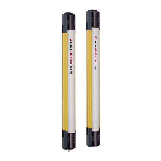
Device Description
Device Overview
Provides a summary of the MLD 300 and MLD 500 series functions and features.
Connection Technology
Describes the M12 connectors and pin assignments for various device models.
Display Elements
Details operating indicators, LED meanings, and 7-segment display codes for diagnostics.
Integrated Laser Alignment Aid
Explains the optional laser aid for precise transmitter-receiver alignment.
Functions
Start/Restart Interlock
Describes the safety function preventing automatic system restart after interruptions.
Contactor Monitoring
Explains the monitoring of feedback circuits for connected contactors.
Signal Output
Details the signal output reporting the status of the safety sensor's OSSDs.
Range Switching
Explains how to adjust the operating range via the transmitter's PIN4.
MultiScan Mode
Describes the mode increasing availability by filtering short interruptions.
Periodic Function Test
Details the test input for periodic function tests on specific models.
Muting
Covers temporary suppression of protective function for object transport.
Applications
Access Guarding
Illustrates MLD safety sensors used for protecting danger zone access points.
Mounting
Arrangement of Transmitter and Receiver
Guides on mounting safety sensors with adequate safety distances and considerations.
Arrangement of the Muting Sensors
Provides instructions for selecting and arranging muting sensors for proper function.
Mounting the Safety Sensor
Details the procedure for selecting mounting locations and types of fasteners.
Electrical Connection
Pin Assignment Transmitter and Receiver
Details M12 connector pin assignments for transmitters, receivers, and transceivers.
Selecting Contactor Monitoring and Start/Restart Interlock
Explains configuration of EDM and RES via pins 1, 3, and 4.
Selecting the Muting Operating Modes
Describes how to select operating modes for muting functions using pins and bridges.
Starting Up the Device
Switching On
Lists requirements and steps for powering up the safety sensor.
AS-i Connection Start-up
Guides on initial commissioning and addressing for AS-i connected sensors.
Aligning the Safety Sensor
Covers prealignment and alignment procedures for optimal sensor positioning.
Aligning Without Integrated Laser Alignment Aid
Details alignment using LED indicators when no laser aid is present.
Aligning With Integrated Laser Alignment Aid
Explains precise alignment using the built-in laser aid for complex setups.
Start/Restart Button
Describes the function of the button for unlocking interlocks and restarting muting.
Testing
Before Initial Start-up and Following Modifications
Outlines essential tests required before initial use or after modifications.
To Be Performed Periodically by Competent Persons
Defines periodic testing responsibilities and intervals for qualified personnel.
Periodically by the Operator
Provides operator checklists for routine safety sensor function checks.
Annual Testing of Safe Switch-off of the AS-i Connection
Specifies annual testing procedures for AS-i safety monitor switch-off.
Maintenance
Troubleshooting
What to do in case of failure?
Guides on identifying and resolving faults using display elements and error messages.
Operating Indicators of the LEDs
Explains the meaning of LED states for transmitters and receivers.
Error Messages 7-Segment Display
Lists error codes and corresponding causes/measures for 7-segment displays.
Multicolor Indicator
Details the meaning of the multicolor indicator states on specific models.
Error Message Query via AS-Interface
Explains how to query interfering signal information using the AS-i master.
Disposing
Service and Support
Technical Data
General Specifications
Lists technical parameters like beam data, safety ratings, and operating conditions.
Dimensions, Weights
Provides physical dimensions and weight specifications for various models.
Dimensioned Drawings: Accessories
Presents detailed drawings of mounting accessories and their dimensions.
Order Guide and Accessories
EC Declaration of Conformity
Table of Contents
Save PDF
Print
Rename the bookmark
Delete bookmark?
Delete from my manuals?
Login
Sign In
OR
Sign in with Facebook
Sign in with Google
Upload manual
Upload from disk
Upload from URL
Need help?
Do you have a question about the MLD 500 and is the answer not in the manual?
Questions and answers