Table of Contents
Advertisement
"The Right Control for Your Application."
KB Electronics, Inc.
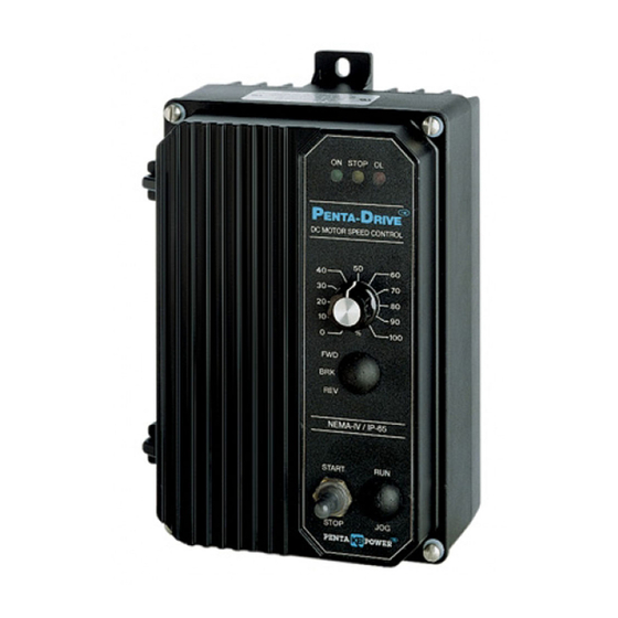
KBPC-240D (Part Nos. 9338 and 9342) Installation and Operation Manual Supplement
This supplement is for Model KBPC-240D Installation and Operation Manual (Part No. A40400) until the new manual is available. The manual
must be read and understood before operating this drive. For further assistance, contact our Sales Department at 954-346-4900 or Toll Free
at 800-221-6570 (outside Florida).
This drive has been converted to Surface Mount Technology (SMT). All trimpots have been moved and aligned at the top of the PC board.
A Run Relay has been added, which can be used to turn equipment "on" or "off" as a function of drive status (Off, Stop, Run). The General
Performance Specifications, Electrical Ratings, Mechanical Specifications, and Connection Diagrams have not changed. The Parts List (Table
11, on pages 17 and 18) and Schematic (Figure 16, on page 19) in the manual no longer apply to this drive and should not be used. See
Figure 1 for the location of the Run Relay Output Contacts, Trimpots, and Jumpers (replaces Figure 1, on page 3, in the manual). See Figure
1 for the Run Relay Output Contacts ratings. See Table 1 for the drive operating conditions and Run Relay Output Contacts status.
TABLE 1 – DRIVE OPERATING CONDITION AND RUN RELAY OUTPUT CONTACTS STATUS
Drive Operating Condition
Power Off
Run Mode
Stop Mode
Trip
(A42144) – Rev. D00 – 1/6/2010
PRODUCT UPDATES
Run Relay Added
FIGURE 1 – DRIVE LAYOUT
Description
Main Power Disconnected
Normal Drive Operation
Selected by Operator
Drive Tripped
12095 NW 39 Street, Coral Springs, FL 33065-2516
Telephone: 954-346-4900; Fax: 954-346-3377
SMT Construction
Normally Open Contact
Open
Closed
Open
Open
www.kbelectronics.com
Normally Closed Contact
Closed
Open
Closed
Closed
Page 1 of 1
Advertisement
Chapters
Table of Contents

Related Manuals for KB Electronics 9338


Summarization of Contents
KBPC-240D Simplified Operating Instructions
Connections
Details on connecting AC line, motor armature, and field wiring for different motor types.
Speed or Torque Mode
Setting the drive mode using Jumper J1 for speed or torque control operations.
Motor Current
Selection of Jumper J4 for motor current rating and its impact on current limit.
Trimpot Settings
Factory settings for trimpots and requirement for readjustment based on application.
Diagnostic LEDs
Observing LED indicators to verify control function and status after power-up.
Armature Fuse
Importance of installing the correct armature fuse for control operation.
Start/Stop Switch
Using the built-in manual start/stop switch and overriding its function.
Safety Warning
General Information
Overview of the KBPC Series Nema 4X control, its features, and modes of operation.
Setting Selectable Jumpers
Control Mode Selection
Setting Jumper J1 for Speed (SPD) or Torque (TRQ) control mode.
AC Line Voltage Input
Selecting input AC line voltage (115V or 230V) using Jumpers J2A and J2B.
Armature Voltage and Feedback
Setting J3 for armature voltage and tach-generator feedback selection.
Armature Current Selection
Using Jumper J4 to select armature current and its relation to motor horsepower.
Current Limit Mode
Selecting between Timed Current Limit (TCL) and Non-Timed Current Limit (NTCL).
Tach-Generator Voltage
Selecting J6 for tach-generator voltage and calculating external resistor values.
Signal Input Voltage
Configuring J7 for analog voltage input (0-5V or 0-10V).
Wiring
AC Line Connection
Connecting AC Line power to terminals L1 and L2, ensuring correct voltage setting.
Motor Armature Connection
Connecting motor armature leads to A1 and A2, warning against armature switching.
Field Connections (Shunt Wound)
Wiring motor shunt field for 90VDC and 180VDC motors with full or half voltage.
Ground Connection
Proper grounding of the control unit by connecting to the green ground screw.
DC Tach-generator Input
Connecting tach-generator feedback signal to terminal block TB3.
Main Potentiometer Connection
Connecting the main potentiometer or a remote potentiometer.
Remote Start/Stop Switch
Wiring a remote switch for Start/Stop functions.
Inhibit Circuit
Using the inhibit circuit to electronically stop the control.
Enable Circuit
Using the enable circuit to start and stop the control.
Fusing
AC Line Fusing
Electrical codes require fusing for ungrounded conductors; control does not have internal AC fuses.
Armature Fusing
Importance of armature fuse installation and fuse chart for motor ratings.
Trimpot Adjustments
Minimum Speed (MIN)
Setting the minimum speed by adjusting the MIN trimpot.
Maximum Speed (MAX)
Setting the maximum speed by adjusting the MAX trimpot.
Acceleration (ACCEL)
Adjusting the ACCEL trimpot to set the time for reaching full output.
Deceleration (DECEL)
Adjusting the DECEL trimpot to set the time for slowing down to minimum speed.
Current Limit (CL)
Setting the maximum DC current draw for the motor using the CL trimpot.
IR Compensation (IR)
Stabilizing motor speed under varying loads using the IR comp circuit.
Timed Current Limit (TCL)
Setting the time delay for the drive to trip out in current limit.
Jog Speed (JOG)
Setting the jog speed when the optional RUN-STOP-JOG switch is installed.
Function Indicator Lamps
Power On Indicator (ON)
The GREEN LED indicating AC line connection to the control.
Stop Indicator (STOP)
The YELLOW LED indicating the control is in STOP mode.
Overload Indicator (CL)
The RED LED indicating motor overload or current limit activation.
Optional Accessories
RUN-STOP-JOG Switch
Provides momentary jog speed for inching machines into position.
Forward-Brake-Reverse Switch
Provides reversing function with dynamic braking.
Signal Isolator
Required for remote nonisolated analog signals, accepts various voltage/current signals.
Auto/Manual Installation Kit
Facilitates mounting of KBSI-240D Signal Isolator with Auto/Man switch.
ON/OFF AC Line Switch
Provides a positive AC Line disconnect option.
RFI Filter
Meets CE directives requirements for RFI filtering.
Electronic Forward-Brake-Reverse
Provides electronic reversing with solid-state dynamic braking.
Wiring
AC Power Connection
Connecting the KBSI-240D to 115V or 230V AC power supply.
Input Terminals
Connecting input signals to terminals 5 through 8 based on signal level.
Current Signal Input
Connecting and calibrating the signal isolator for 4-20 mA current input.
Voltage Input Signal
Connecting and calibrating the signal isolator for various DC voltage input ranges.
Need help?
Do you have a question about the 9338 and is the answer not in the manual?
Questions and answers