Table of Contents
Advertisement
Advertisement
Table of Contents
Troubleshooting

Related Manuals for red lion GEMINI 2000


Summary of Contents for red lion GEMINI 2000
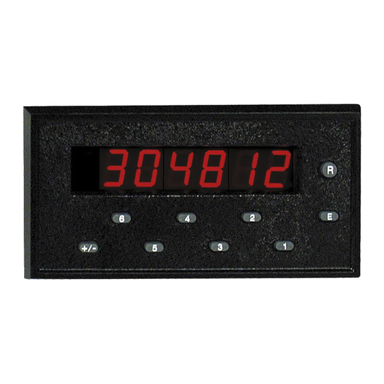
- Page 1 THE ASTRO LINE SERIES GEMINI 1000/2000 INSTRUCTION MANUAL...
- Page 2 INTRODUCTION The Gemini 1000 and 2000 are both units in a multi-purpose series of industrial control units that are field-programmable to solve multiple applications. This series, known as the Astro-Line family of products, is built around the concept that the end user has the capability to program different personalities and functions into the unit in order to adapt to different indication and control requirements.
-
Page 3: Table Of Contents
Programming The Gemini 1000/2000 ........ -
Page 4: General Description
GENERAL DESCRIPTION The Gemini is a two input, microprocessor-based device which offers the Preset and reset behavior of the output(s) and display are completely features and performance of a single (GEM 1000)/dual (GEM 2000) level preset programmable. The preset(s) can have a value ranging from -999999 to +999999. counter or sample time, rate indicator. -
Page 5: Programming The Personality
Data for the presets, scale factor, and time delays are entered differently. Each PROGRAMMING THE PRESETS, SCALE FACTOR, & digit key controls the digit on the display directly above it. Changing the digits OUTPUT TIME DELAYS can be done by repeatedly pressing the key beneath the digit position you wish to The scale factor and preset values are commonly reprogrammed on a daily change or by merely holding it down. - Page 6 PROGRAMMING THE PRESETS, SCALE FACTOR, & OUTPUT TIME DELAYS (Cont’d) Note: A time delay value of zero cannot be programmed into the Gemini. If a value of 0 is entered into the display and the “E” key is pressed, the unit will continue to use the previous time delay value.
-
Page 7: Factory Settings
FACTORY SETTINGS Keys Struck Display Description Personality selected as Counter Count with Inhibit Count on one edge of input (no doubling) Scale Multiplier of 1.0 Leading zero blanking and no decimal point Manual reset-to-zero, as long as button remains PUSHED Output 1 terminates at Reset, Normal Output Phase 0.10 second Output 1 time delay. -
Page 8: Operator Accessible Functions With Programming Disabled
OPERATOR ACCESSIBLE FUNCTIONS WITH used in conjunction with any front panel disable mode. The combination of manual PROGRAMMING DISABLED and remote inputs provides a high level of security without sacrificing flexibility. (For details on keyboard entry, see preceding section) DIAGNOSTICS, SELF TEST, & “WATCHDOG” TIMER One of the important features of the Gemini is the ability to disable The security and integrity of the Gemini is further enhanced by its self-test, programming. -
Page 9: Input Circuitry & Set-Up
An automatic exit will take place after six seconds or immediately if the Program Disable terminal is connected to common. Normal length of display time for each of the patterns is approximately 0.5 seconds. Rapidly pressing the “+/-” key during self test can speed up the process. INPUT CIRCUITRY &... -
Page 10: Programming Instructions For The Counter Version Of The Gemini 1000/2000
PROGRAMMING INSTRUCTIONS FOR THE COUNTER VERSION OF THE GEMINI The first part of this section provides detailed description of the function [43 3] TWO (2) INPUT ANTI-COINCIDENCE ADD/SUBTRACT - This mode command codes for counting modes, reset modes, output terminations, etc. Then, effectively separates count pulses which may simultaneously appear at the two inputs. -
Page 11: Codes 51, 52, 53, 54, & 55
CODE 44 - NUMBER OF COUNT EDGES [46 1] [46 2] The Gemini can be programmed for either single edge or two edge (doubling) LEADING ZERO [46 3] 0.0 0 counting. The number of count edges cannot be set when the count mode is BLANKING 0.0 0 0 [46 4]... - Page 12 CODE 51 - RESET MODES (Cont’d) preset is reached. The reset condition of the output is output on. (Note: The state of the relay, if used, is also reversed.) A “-” sign in front of the mode identifier [51 3] AUTOMATIC RESET TO ZERO AFTER OUTPUT TIME DELAY - will provide for reverse phase operation.
- Page 13 1] TERMINATE AT OUTPUT 1 START - Output 2 will terminate when [52 -1] [52 -2] Output 1 starts. [52 -3] These modes are the same as above with the exception [54 2] TERMINATE AT OUTPUT 1 END - Output 2 will terminate when that the output is set for reverse phase operation.
-
Page 14: Codes 61, 66, Preset Values, & Scale Factor
CODE 55 - OUTPUT 2 TIME DELAY (GEMINI 2000 Only) [66 2] PRESET PROGRAMMING AND RESET ENABLED - In this mode, manual reset and the programming of the Preset Values are enabled. The Gemini 2000 has the capability of varying the output time delay from 0.01 [66 3] SCALE FACTOR PROGRAMMING AND RESET ENABLED - In this second to 599.99 seconds. - Page 15 It is important to note that the precision of an application cannot be improved by using a scale factor greater than one. To accomplish greater precision, more pulse information must be generated per measuring unit. For example, if 5 pulses are being received per foot of material, the precision of 10th of feet cannot be attained by simply programming a 2.000 scale factor, even though the display is reading in tenths.
-
Page 16: Dual Preset Counting & Programming Application Example
DUAL PRESET COUNTING & PROGRAMMING APPLICATION EXAMPLE A typical industrial application for Gemini 2000 will require both a slow down output and a final stop output. The Gemini can easily be programmed to solve this requirement. For instance, let’s look at a textile web process that requires a dual output as the web progresses to the proper length. - Page 17 HARDWARE SET-UP STEP 6 - Enter function code 51 (Reset Modes), and enter a mode identifier of 2 for Manual reset to Preset 2. This mode was chosen to allow set-up time for a The application drawing shows how the hardware for this system is to be new roll or take-up spool.
-
Page 18: Programming Instructions For The Rate Indicator Version Of The Gemini 1000/2000
PROGRAMMING INSTRUCTIONS FOR THE RATE INDICATOR VERSION OF THE GEMINI The first part of this section provides detailed descriptions of the function [45 1] SCALE MULTIPLIER VALUE OF 1 - This value multiplies the internal command codes for scale multiplier, leading zero blanking, output terminations, rate by 1. - Page 19 the case with all standard rate indicators. In order to ensure this type of operation, Scale Factor), the output is not activated when the rate value is more positive than the preset value. When the rate value is more negative than or equal to the it is important that the reset Disable/Enable switch be disabled to preclude any preset, the output is activated.
- Page 20 CODE 54 - OUTPUT 2 TERMINATION MODES (Gemini 2000 Only) The Gemini 2000 has two standard Output 2 Termination Modes when [54 4] TERMINATE AT MANUAL RESET END - This mode is like the preceding output mode, except the output deactivates when the reset ends. The operating as a rate indicator.
- Page 21 CODE 63 - SAMPLE TIME [66 -1] The Gemini offers six different lengths of sample times. They are 1 second; 2 [66 -2] These Modes are the same as above with the exception that manual reset is disabled. seconds; 5 seconds; 10 seconds; 20 seconds; and 50 seconds. Sample Time is defined [66 -3] [66 -4] as the time period allowed for input pulses to accumulate.
-
Page 22: Dual Preset Rate Programming Application Example
DUAL PRESET RATE PROGRAMMING APPLICATION EXAMPLE A typical industrial Dual preset rate indicator application would be the speed control of a web press operation in a newspaper plant. The Gemini 2000 as pictured, is programmed to read out in feet/min. every two seconds. The input is from the rotary pulse generator that is attached on the drive roll. - Page 23 HARDWARE SET-UP STEP 3 - Enter code 45 (Scale Multiplier Values), and enter a mode identifier of 1 for a scale multiplier of 1. The application drawing shows how the hardware for this system is to be STEP 4 - Enter code 46 (Decimal Point and Leading Zero Blanking) and enter 1 connected.
-
Page 24: 20 Ma Current Loop Serial Communications (Gemini 2000 Only)
GEMINI 2000 20 mA CURRENT LOOP COMMUNICATIONS FIG. 1: DATA FORMAT-10 BIT FRAME [300, 600, 1200, 2400 Baud] The Gemini 2000 20 mA Current Loop Communications Option allows a “two-way” serial communications link to be established in order to monitor or change the count value, Presets and Scale Factor from a remote location. - Page 25 The command string is constructed by using the above commands and value As shown, all commands must be terminated with a “Command Terminator” identifiers, along with the data values that are required. Data values may or may (* or 2AH). The Gemini 2000 will not process the command until the terminator not contain the decimal point if a decimal point is programmed into the Gemini is sent.
-
Page 26: Receiving Data From The Gemini 2000
RECEIVING DATA FROM THE GEMINI 2000 When the Print ID switch is in the down position, the unit will not transmit the characters before the data value (address, Value ID, spaces) or the 400 msec Data is transmitted from the Gemini 2000 when a “Transmit Value” or printer delay. -
Page 27: Current Loop Installation
CURRENT LOOP INSTALLATION WIRING CONNECTIONS When wiring the 20 mA current loop, remove the 7-position terminal block (TBD), located on the right side of the top board. Refer to the numbers listed with the terminal descriptions below or on the top label, and install each wire in its proper location on the terminal block. -
Page 28: Current Loop Installation
CURRENT LOOP INSTALLATION (Cont’d) When the switch is in the down position, the Gemini 2000 will transmit only the data value, without the unit address and data ID. The 400 msec delay, described SERIAL DIP SWITCH SET-UP above, will not be inserted. This switch position usage is intended for applications The Serial DIP switches are accessible through the side of the Gemini 2000. -
Page 29: Communications Applications
COMMUNICATIONS APPLICATIONS CONNECTING TO AN RLC PRINTER One or several Gemini 2000s (with Serial Communications option) can be set up to operate with an RLC Model DMPC printer. The two applications show the wiring diagrams for single and multiple Gemini hookups to the printer. Both loops (transmit and receive) are used with the Model DMPC printer. - Page 30 PROCESS MONITORING SYSTEM Five Gemini 2000s with 20 mA Current Loop Option, are The drawing below shows the Current Loop set-up. Each used to monitor and control parts packaging machines in a Gemini 2000 is given an address and the Serial DIP switches are plant.
-
Page 31: Troubleshooting Gemini Serial Communications
“Sending Commands & Data to the Gemini” section for command structure. 5. If two-way communications are to be established between the Gemini and a If the unit does not pass this test, contact your local Red Lion Controls computer, try getting the computer to receive transmissions from the Gemini distributor. -
Page 32: Appendix "A" - Installation & Input Configuration Switch Set-Up
APPENDIX “A” - INSTALLATION & INPUT CONFIGURATION SWITCH SET-UP Installation Environment Before installing the Gemini into the panel, the user should first become The unit should be installed in a location that does not exceed the maximum familiar with the unit. It may also be desirable to program the unit for the operating temperature and provides good air circulation. - Page 33 GEMINI 1000 BLOCK DIAGRAM –31–...
- Page 34 GEMINI 2000 BLOCK DIAGRAM –32–...
- Page 35 SELECT AC POWER (115/230 VAC) Shield Termination The AC power to the unit must be selected for either 115 VAC or 230 VAC. EMC compliance installation testing had the drain wire for the shielded cable The selector switch is located through an access slot on the side of the case (See terminated as shown.
- Page 36 Additional EMC Installation Guidelines several times or use multiple cores on each cable for additional protection. Install line filters on the power input cable to the unit to suppress power line Although this unit is designed with a high degree of immunity to interference.
- Page 37 PRIMARY A.C. POWER WIRING SERIAL COMMUNICATIONS For best results, the A.C. primary power should be relatively “clean” and within The Gemini 2000 can be purchased with 20 mA Current Loop Option. On the specified +/-10% variation limits. Drawing power from heavily loaded circuits these units, refer to the 20 mA Current Loop section for installation and or from circuits that also power loads that cycle on and off, should be avoided.
- Page 38 INSTALLATION & REMOVAL OF THE RELAY BOARD NOTES: 1. SENSOR VOLTAGE AND CURRENT To install the relay board, locate the relay opening at the lower right-hand The +12 V sensor supply voltage on the “DC OUT” terminal is nominal with corner, on the back of the Gemini.
- Page 39 GEMINI 1000 CONNECTIONS & CONFIGURATION SWITCH SET-UPS FOR VARIOUS SENSOR OUTPUTS (SEE NOTE 5) –37–...
- Page 40 GEMINI 2000 CONNECTIONS & CONFIGURATION SWITCH SET-UPS FOR VARIOUS SENSOR OUTPUTS (SEE NOTE 5) –38–...
- Page 41 GEMINI 1000 SENSOR INPUT CONNECTIONS & INPUT CONFIGURATION SWITCH SET-UP The accompanying diagram shows the details of the count Input A and magnetic pickup circuit. The schematic circuit for Input B is almost identical to that of Input A, with the exception that Input B does not have the Magnetic Pickup circuitry paralleled with it.
- Page 42 GEMINI 2000 SENSOR INPUT CONNECTIONS & INPUT CONFIGURATION SWITCH SET-UP The accompanying diagram shows the details of the count Input A and magnetic pickup circuit. The schematic circuit for Input B is almost identical to that of Input A, with the exception that Input B does not have the Magnetic Pickup circuitry paralleled with it.
-
Page 43: Appendix "B" - Specifications & Dimensions
APPENDIX “B” - SPECIFICATIONS & DIMENSIONS 1. DISPLAY: 6-digit, 0.56" (14.2 mm) High LED display. 6. MAXIMUM COUNT RATES: 2. POWER REQUIREMENTS: Uni or Bi-Directional Modes - 9,000 cps, 8,000 cps (X2) AC Power: Switch selectable 115/230 VAC (+/-10%), 50/60 Hz, 20 VA 2-Input Anti-Coincidence Modes - 5,000 cps, 4,000 cps (X2) DC Power: 11 to 14 VDC @ 0.7 amp maximum Quadrature Modes - 5,000 cps (X1), 4,000 cps (X2 or X4) - Page 44 8. SERIAL COMMUNICATIONS (Optional): (Cont’d) Emissions to EN 50081-2 Serial Hardware Specifications - RF interference EN 55011 Enclosure class A SO - Output Transistor Rating: V = 30 VDC, V = 1 V at 20 mA. Power mains class A (Can address 16 units in a loop) Notes: SI - Input Diode Rating: VF = 1.25 V...
-
Page 45: Appendix "C" - Troubleshooting Guide
APPENDIX “C” - TROUBLESHOOTING GUIDE The majority of difficulties arising with the Gemini 2000 are related to incorrect power hook-up and programming set-up. Always check all connections, function codes, Scale Factor, and presets as a first step in troubleshooting. Before applying power, double check all wiring. Improper AC voltage or AC connections may result in permanent damage to the unit. - Page 46 APPENDIX “C” - TROUBLESHOOTING GUIDE (Cont’d) PROBLEM POSSIBLE CAUSE REMEDIES UNIT WILL NOT ACCEPT THE 1. When scale factors greater than 1 are used, 1. Unit automatically adjusts preset value to be DESIRED PRESET VALUE evenly divisible by the scale factor value. the preset value must be evenly divisible by the scale factor value.
- Page 47 APPENDIX “C” - TROUBLESHOOTING GUIDE (Cont’d) PROBLEM POSSIBLE CAUSE REMEDIES CANNOT PROGRAM CODE 52 - 1 , 2 1. 54 -6 is programmed. 1. Change 54 then program 52. 2. Unit is in tachometer mode. CANNOT PROGRAM CODE 52 - 6 1.
- Page 48 APPENDIX “D” - GEMINI FUNCTION COMMAND CODE SUMMARY CODE MODE DESCRIPTION COMMENTS UNIT PERSONALITY Counter Rate Automatically selects [51 1], [52 6] & [54 6] if [54 1,2] or[52 1,2] was programmed. INPUTS A & B RESPONSE MODES (counter only) Count with Inhibit Input A = Count, Input B = Inhibit Count with Up/Down Control...
- Page 49 APPENDIX “D” - GEMINI FUNCTION COMMAND CODE SUMMARY (Con’t) CODE MODE DESCRIPTION COMMENTS RESET MODES (+) Maintained Unit will remain reset as long as reset is activated. (-) Momentary Unit will reset instantly and will start counting again even if reset is still activated.* +/-1 Manual to zero...
- Page 50 APPENDIX “D” - GEMINI FUNCTION COMMAND CODE SUMMARY (Con’t) CODE MODE DESCRIPTION COMMENTS OUTPUT 2 TERMINATION (Con’t) +/-5 Terminate after Output 2 Time Delay +/-6 Boundary Automatically selects [51 1]. OUTPUT 2 TIME DELAY (Gemini 2000 Only) Range 0.01 to 599.99 sec. RIGHT-HAND DUMMY ZEROS 1 Dummy Zero 2 Dummy Zeros...
-
Page 51: Appendix "E" - Scaling For Rate Indication
APPENDIX “E” - SCALING FOR RATE INDICATION APPLICATION EXAMPLE [A] The Gemini offers a simplified method of scaling a rate indication display. This unit offers the capability to monitor the entire range of any linear rate PARAMETERS AT MONITORED SPEED process. - Page 52 4. Any calculated scale factor may be divided by a factor of 10, by programming In this application, the 5.9999 scale factor has been exceeded. To complete the Function Code 61 (dummy right-hand zeros) to [61 1], which will display a requirements, the calculated scale factor 8.68 is divided by 2, and the resultant constant zero in the least significant digit.
- Page 53 APPENDIX “F” - GEMINI 1000 PROGRAMMING CHART CARD -51-...
- Page 54 APPENDIX “F” - GEMINI 1000 PROGRAMMING CHART CARD –52–...
- Page 55 APPENDIX “F” - GEMINI 2000 PROGRAMMING CHART CARD -53-...
- Page 56 APPENDIX “F” - GEMINI 2000 PROGRAMMING CHART CARD -54-...
-
Page 57: Appendix "F" - Gemini 1000/2000 Programming Charts
GEM20060 GEM20160 Gemini 1000 Relay Board RLYBD000 ¾ Gemini 2000 Relay Board RLYBD002 ¾ For Information on Pricing, Enclosures, Base Mount Kits, & Panel Adapter Kits, refer to the Red Lion Controls Catalog or contact your local RLC distributor. –55–... - Page 58 This page is intentionally left blank. -56-...
- Page 59 Company’s option. The Company disclaims all liability for any affirmation, promise or representation with respect to the products. The customer agrees to hold Red Lion Controls harmless from, defend, and indemnify RLC against damages, claims, and expenses arising out of...
- Page 60 GEM2 / IM - L 4/02 DRAWING NO. LP0098 Red Lion Controls Red Lion Controls France Red Lion Controls BV 20 Willow Springs Circle 56 Boulevard du Courcerin, Batiment 21, Databankweg 6C York PA 17402 ZI Pariest F-77183 Croissy Beaubourg...
Need help?
Do you have a question about the GEMINI 2000 and is the answer not in the manual?
Questions and answers