
Related Manuals for POOLEX 40


Summary of Contents for POOLEX 40
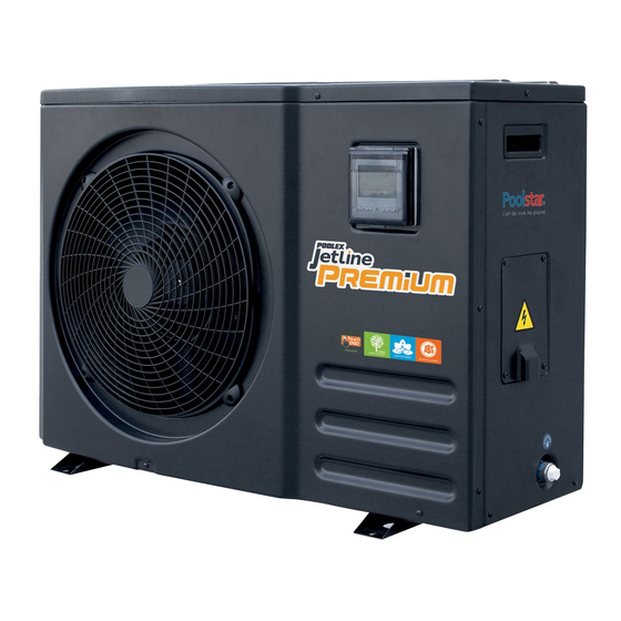
- Page 1 INSTALLATION AND USER MANUAL for your heat pump Models: 40 / 50 / 70 / 90 / 110 / 130 / 160 / 160 Tri / 180 Tri / 220 Tri...
- Page 3 These are the result of many years of research in the field of design and production of heat pumps for swimming pools. Our aim is to provide you with an exceptional high performance quality product. We have produced this manual with the utmost care so that you get maximum benefit from your Poolex heat pump.
- Page 4 They must be given to the installer and retained by the user. If the manual is lost, please consult the website: www.poolex.co.uk The instructions and recommendations contained in this manual should be read carefully and understood since they provide valuable information concerning the heat pump’s safe handling and operation. Keep this manual in an accessible place for easy future reference.
-
Page 5: Table Of Contents
Contents 1. General ......................................6 General Terms of Delivery ................................. 6 Safety instructions..................................6 Water treatment ..................................7 2. Description ...................................... 8 Package contents ..................................8 General characteristics ................................8 Technical specifications ................................9 Unit dimensions ..................................10 Exploded view ....................................11 3. -
Page 6: General
1. General 1.1 General Terms of Delivery All equipment, even if shipped ‘free of carriage and packing’, is dispatched at the consignee’s own risk The person responsible for receiving the equipment must carry out a visual inspection to identify any dam- age to the heat pump during transport (refrigerant system, body panels, electrical control box, frame). -
Page 7: Water Treatment
The low and high side test pressure must not exceed 42 bar. 1.3 Water treatment Poolex heat pumps for swimming pools can be used with all types of water treatment systems. Nevertheless, it is essential that the treatment system (chlorine, pH, bromine and/or salt chlorinator meter- ing pumps) is installed after the heat pump in the hydraulic circuit. -
Page 8: Description
4 anti-vibration pads (fastenings not supplied) 2.2 General characteristics A Poolex heat pump has the following features: CE certification and complies with the RoHS European directive. High performance with up to 80% energy savings compared to a conventional heating system. -
Page 9: Technical Specifications
Unit dimensions L x W x H (mm) 895x370.5x610 923x410x661 1215x485x713 1215x505x866 Unit weight (kg) Sound pressure level at 1 m (dBA) <47 <48 <48 <49 <49 <50 <50 <50 <51 <51 Sound pressure level at 4 m (dBA) <37 <38 <38 <39 <39 <40 <40... -
Page 10: Unit Dimensions
2. Description 2.4 Unit dimensions dimensions in mm Jetline Premium Jetline Premium Jetline Premium Jetline Premium Model 40 / 50 70 / 90 / 110 130 / 160 / 160 Tri 180 Tri / 220 Tri 1215 1215 370.5 346.5 424.5... -
Page 11: Exploded View
2. Description 2.5 Exploded view 1. Front panel 11. Top panel 2. Fan protective grille 12. Electrical terminal block 3. Fan blade 13. Pressure gauge 4. Fan motor 14. Right hand grip 5. Fan support 15. Electrical box cover 6. Left side panel 16. -
Page 12: Installation
Dimensions in mm. Place nothing less than one metre in front of the heat pump. Leave 50 cm of empty space around the sides and rear of the heat pump. Do not leave any obstacle above or in front of the unit! -
Page 13: Installation Layout
3. Installation 3.3 Installation layout Heat pump Automated treatment system 4-way valve (salt chlorinator, metering pump) Valve 1 Valve 5 Valve 3 Valve 2 Water outlet Water intake Elevating studs Valve 4 Drain Condensation Circulating Filtration plug draining pump FROM THE POOL TOWARDS THE POOL Valves 1, 2 and 3: Bypass valves Valves 4 and 5: Regulating valves... -
Page 14: Hydraulic Connection
3. Installation WARNING: Installation must be carried out by a qualified engineer. This section is provided for information purposes only and must be checked and adapted if necessary according to the actual installation conditions. 3.6 Hydraulic connection By-Pass assembly Open valve The heat pump must be connected to the pool by Half-open valve means of a By-Pass assembly. - Page 15 3. Installation By-Pass assembly for one heat pump TOWARDS THE POOL Automated treatment system POOL Filtration + Pump FROM THE POOL Half-open valve Open valve By-Pass assembly for more than one heat pump TOWARDS THE POOL Automated treatment system POOL Filtration + Pump FROM THE POOL Half-open valve...
-
Page 16: Electrical Installation
Cable Models Electricity supply Max. current Thermal-magnetic (D diameter curve) protection Jetline Premium 40 RO2V 3x2.5 mm² Jetline Premium 50 RO2V 3x2.5 mm² Jetline Premium 70 10.6 RO2V 3x4 mm² Single phase Jetline Premium 90 12.5 RO2V 3x4 mm² 230V~50Hz Jetline Premium 110 15.4... -
Page 17: Electrical Connection
3. Installation 3.8 Electrical connection WARNING: The heat pump’s power supply MUST be disconnected before any operation. Please comply with the following instructions to electrically connect the heat pump. Step 1: Detach the electrical side panel with a screwdriver to access the electrical terminal block. Step 2: Insert the cable into the heat pump unit by passing it through the opening provided for that pur- pose. -
Page 18: Wall-Mounting The Remote Control
3. Installation 3.9 Wall–mounting the remote control Step 1: Detach the remote control from the machine. Pay WARNING to the communication wire connected to the printed circuit board and separate them carefully. Step 2: Use a screwdriver to open the casing and separate the remote control. Step 3: Drill two parallel holes at eye level: 60 mm centre-to-centre. -
Page 19: Use
4. Use 4.1 Wired remote control Operating mode Water temperature Outside temperature Clock Button: Clock Button: On/Off and Timers Button: Operating Button: mode Programming 4.2 Operating mode selector Before starting, ensure that the filtration pump is working and that water is circulating through the heat pump. -
Page 20: Automatic Mode
4. Use 4.3 Automatic Mode WARNING: Before starting, ensure that the filtration pump is in working order. Step 1: Press once to switch on your pump. Step 2: Press to switch from one mode to another until Automatic mode is displayed. Step 3: Use the arrows select the desired temperature (8-40°C). -
Page 21: Cooling Mode
4. Use 4.4 Cooling mode WARNING: Before starting, ensure that the filtration pump is in working order. Step 1: Press once to switch on your pump. Step 2: Step 3: Press to switch from one mode to another until the cooling mode is displayed. Use the arrows select the desired temperature (8-28°C). -
Page 22: Heating Mode
4. Use 4.5 Heating mode WARNING: Before starting, ensure that the filtration pump is in working order. Step 1: Press once to switch on your pump. Step 2: Step 3: Press to switch from one mode to another until the heating mode is displayed. Use the arrows select the desired temperature (15-40°C). -
Page 23: Setting The Time
4. Use 4.6 Setting the time Set the system clock to local time, as follows: Step 1: With the heat pump switched off, press to set the time. Step 2: When the symbol blinks, press to select the hour. Step 3: Adjust the hours with the buttons Step 4: Press to select the minutes. -
Page 24: Programming Start/Stop
4. Use 4.7 Programming Start/Stop This function is for programming the Start/Stop timing. You can programme up to 3 different Start/Stop timings. Setting is as follows: Step 1: Select the programme to be configured, NB: The remote control - Press twice to select programme 1. -
Page 25: Cancelling A Programme
4. Use 4.8 Cancelling a programme Please use the following example to cancel a programme: Step 1: Select the programme to be cancelled, - Press twice to select programme 1. - Press 4 times to select programme 2. - Press 6 times to select programme 3. -
Page 26: Status Values And Advanced Settings
4. Use 4.9 Status values and advanced settings WARNING: This operation is used to assist servicing and future repairs. The default settings should only be modified by an experienced professional person. The system’s settings can be checked and adjusted via the remote control by following these steps Step 1: Press for 6 seconds to enter the settings verification mode... - Page 27 4. Use Parameters table Factory N° Description Adjustment range Remarks setting 0 = Off Automatic restart Adjustable 1 = On 0 = start only START/STOP times programming Adjustable 1 = daily Adjustment of temperature difference for restart Adjustable from 2 to 10°C 3°C Adjustable Adjustment of compressor shutdown margin...
-
Page 28: Operation
5. Operation 5.1 Operation Conditions of use For the heat pump to operate normally, the ambient air temperature must be between -5°C and 43°C. Recommendations prior to start-up Before activating the heat pump, please: Check that the unit is firmly secured and stable. Check that the gauge indicates a pressure greater than 80 psi. -
Page 29: Servo-Controlling A Circulating Pump
5. Operation 5.2 Servo-controlling a circulating pump If you have connected a circulating pump to terminals P and P , it is automatically electrically powered when the heat pump operates. When the heat pump is on standby, the circulating pump is powered intermittently in order to monitor the water temperature in the pool. -
Page 30: Antifreeze Protection
5. Operation 5.4 Antifreeze protection WARNING: For the antifreeze system to work, the heat pump must be powered and the circulating pump activated. If the circulating pump is servo-controlled by the heat pump, it will be automatically activated. When the heat pump is on standby, the system monitors the ambient temperature and the water tempera- ture in order to activate the antifreeze programme if required. -
Page 31: Maintenance And Servicing
6. Maintenance and servicing 6.1 Maintenance and servicing WARNING: Before undertaking maintenance work on the unit, ensure that you have disconnected the electrical power supply. Cleaning The heat pump’s casing must be cleaned with a damp cloth. The use of detergents or other household products could damage the surface of the casing and affect its properties. -
Page 32: Repairs
7. Repairs WARNING: Under normal conditions, a suitable heat pump can heat the water in a swimming pool by 1°C to 2°C per day. It is therefore quite normal to not feel any temperature difference in the system when the heat pump is working. A heated pool must be covered to avoid any loss of heat. -
Page 33: List Of Faults
7. Repairs 7.3 List of faults 7.2 List of faults Code Fault Possible causes Action 1) Sensor badly connected 1) Reconnect sensor Water intake temperature sensor malfunction 2) Sensor defective 2) Replace sensor 3) PCB defective 3) Replace PCB Water outlet temperature sensor malfunction De-icing temperature sensor malfunction Same causes as P3 Same actions as P3... -
Page 34: Recycling
8. Recycling 8.1 Recycling the heat pump Your heat pump has reached the end of its life and you wish to dispose of it or to replace it. Do not throw it in the rubbish bin. A heat pump must be disposed of separately with a view to its reuse, recycling or upgrading. It contains substances that are potentially hazardous to the environment but which will be eliminated or neutralised by recycling. -
Page 35: Warranty
The Poolstar Company guarantees the original owner against defective materials and faults in the manufac- ture of the Poolex Jetline Premium heat pump for a period of three (3) years. The compressor is guaranteed for a period of five (5) years. -
Page 36: Appendices
GREEN High Pressure Switch Transformer BLACK Low Pressure Switch WHITE BLACK BLACK Wire controller BLACK WHITE ORANGE BLACK WHITE FAN CAPACITOR CAPACITOR BLACK BLUE BLACK P1 P2 Power: AC To pump 220-240V/50Hz Model Poolex Jetline Premium 40, 50 & 70... - Page 37 High Pressure Switch Transformer BLACK Low Pressure Switch WHITE BLACK BLACK Wire controller BLACK WHITE ORANGE BLACK WHITE FAN CAPACITOR BROWN BLACK CAPACITOR BLACK BLUE BLACK P1 P2 Power: AC To pump 220-240V/50Hz Model Poolex Jetline Premium 90, 110 & 130...
- Page 38 10. Appendices Model Poolex Jetline Premium 160...
- Page 39 Ambient temp OUT3 Condenser temp Main control board Outlet water temp BLUE OUT4 Inlet water temp OUT5 BLUE AC-N Model Poolex Jetline Premium 160 BLACK BLACK WHITE GREEN Transformer High Pressure Switch BLACK WHITE Low Pressure Switch BLACK Wire controller...
- Page 40 R410 OZONE FRIENDLY MATERIAL DURABLE SILENT EFFICIENCY TE C H N I C AL S UP P OR T www.poolex.co.uk Poolex is a Poolstar Group trademark www.poolstar.fr...
Need help?
Do you have a question about the 40 and is the answer not in the manual?
Questions and answers