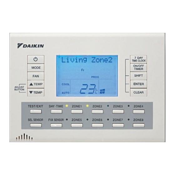
Summary of Contents for Daikin BRC24Z4
- Page 1 INSTALLATION MANUAL ZONE CONTROLLER Air Conditioners MODELS BRC230Z4 BRC230Z8 BRC24Z4 BRC24Z8 BRCSZC PLEASE READ THESE INSTRUCTIONS CAREFULLY BEFORE INSTALLATION. KEEP THIS MANUAL IN A HANDY PLACE FOR FUTURE REFERENCE.
-
Page 3: Table Of Contents
HOW TO INSTALL BRC230Z4 / BRC230Z8........ -
Page 4: Safety Considerations
SAFETY CONSIDERATIONS Please read these “SAFETY CONSIDERATIONS” carefully before installing the zone controller and be sure to install it correctly. After completing the installation, make sure that the zone controller operates properly. Please instruct the customer on how to operate the zone controller. Please inform the customer that they should store this installation manual along with the operation manual for future reference. -
Page 5: Accessories
TO RELAY PCB S19 (4 ZONE) TO P1 P2 TERMINAL NOTE: BLOCK (NOTE1) P1 P2 TERMINAL BLOCK LOCATED IN THE ELECTRICAL TO SUB CONTROLLER BOX OF INDOOR UNIT. TN1, TN2 ONLY USE DAIKIN REMOTE TEMPERATURE (NOTE 2) SENSOR KRCSO1-1 S7 S8 S7 S8 :TERMINAL POST... -
Page 6: How To Install Brc230Z4 / Brc230Z8
HOW TO WIRE & INSTALL BRC230Z4 / BRC230Z8 Note 1: You may find it easier to wire the control box before mounting the box to the indoor unit, for example when the ceiling space is tight. If you choose to wire the control box before mounting it to the indoor unit ensure to allow adequate cable length. - Page 7 Fig.4a Step 4. Pass the remote controller cable through the two open 7 DAY TIME CLOCK ON/OFF MODE TIMER SHIFT TEMP ENTER cable ties (factory supplied). ADJUST BUTTON TEMP CLEAR TEST/EXIT DAY TIME ZONE1 ZONE2 ZONE3 ZONE4 SEL SENSOR FIX SENSOR ZONE5 ZONE6 ZONE7...
-
Page 8: How To Install Brc24Z4 / Brc24Z8
HOW TO WIRE & INSTALL BRC24Z4 / BRC24Z8 Note 1: You may find it easier to wire the control box before mounting the box to the indoor unit, for example when the ceiling space is tight. If you choose to wire the control box before mounting it to the indoor unit ensure to allow adequate cable length. - Page 9 Step 4. Fig.4a Pass the remote controller cable through the two open cable ties (factory supplied). 7 DAY TIME CLOCK ON/OFF MODE TIMER SHIFT TEMP ENTER ADJUST BUTTON TEMP CLEAR Connect the remote controller cable to the Interface TEST/EXIT DAY TIME ZONE1 ZONE2 ZONE3...
-
Page 10: Installing Remote Sensor 1 & 2
INSTALLING REMOTE SENSOR 1 & 2 Step 1. Using Daikin option KRCSO1-1 cut plug off lead. (Fig.7) Step 2. KRCSO1-1 Carefully strip the insulation of the leads exposing the core wire. Insert the 2 stripped wires into the two terminal holes of terminal block TN1. - Page 11 Auto fan function with air sampling mode Sens” (Indoor unit air temperature sensor) is selected. Auto fan function will activate once the set point Auto fan function will operate the same as Std. fan temperature is achieved (thermo off) and will function when other sensors are selected.
-
Page 12: Dsi Switch Settings
Duct Configuration Layout 1 Note 6. ZONE 1 Layout 1 (No Common Zone) It is recommended to set the field set code to “Keep 1 Zone ON” One zone will remain on at all times when the air conditioning unit is in operation to ensure damage to the ducting system will not occur by over pressurising. -
Page 14: Controller Mounting Bracket
CONTROLLER MOUNTING BRACKET Hole ush 18mm with HOLE top of bracket WALL Installed controller height 18mm Do not cut hole above height of Earth shield spade receptacle is above top of mounting bracket. bracket. used only when extension cable (BRCW902A15) is installed. When BRCW902A15 is not used tuck insulated spade receptacle in wall cavity... -
Page 15: Sub Controller Instructions
TO P1 P2 TERMINAL Remote controller wiring NOTE: BLOCK (NOTE1) P1 P2 TERMINAL BLOCK LOCATED IN THE ELECTRICAL TO SUB CONTROLLER BOX OF INDOOR UNIT. TN1, TN2 ONLY USE DAIKIN REMOTE TEMPERATURE (NOTE 2) SENSOR KRCSO1-1 S7 S8 S7 S8 :TERMINAL :CONNECTOR... - Page 16 DAIKIN AUSTRALIA PTY. LIMITED 77-83 Alfred Road, Chipping Norton, NSW 2170 Australia Phone: 1300 78 72 66 www.daikin.com.au DAIKIN INDUSTRIES LTD. Head office: Umeda Centre Building, 4-12 Nakazaki-Nishi 2 chome, Kita-ku, Osaka, 530-8323 Japan Tokyo office: Shinjuku Sumitomo Building, 6-1 Nishi-Shinjuku...


Need help?
Do you have a question about the BRC24Z4 and is the answer not in the manual?
Questions and answers