Table of Contents
Advertisement
40MKCB / 24AHA4 / 124ANS
40MKQB / 25HHA4 / 224ANS
High---Wall Ductless Split System
Sizes 18 to 32
TABLE OF CONTENTS
. . . . . . . . . . . . . . . . . . . . . . . . . . . . . . . . . . .
. . . . . . . . . . . . . . . . . . . . . . . . . . . . . . . . . .
. . . . . . . . . . . . . . . . . . . . . . . . . . . . . . . . . . . . . .
. . . . . . . . . . . . . . . . . . . . . . . . . . . . . . . . . . . . .
. . . . . . . . . . . . . . . . . . . . . . . . . . . . . . . .
. . . . . . . . . . . . . . . . . . . . . . . . . . . . .
. . . . . . . . . . . . . . . . . . . . . . . . . . . . . .
. . . . . . . . . . . . . . . . . . . . . . . . . . . . . . . . . . . . . . .
SAFETY CONSIDERATIONS
Installing, starting up, and servicing air- -conditioning equipment
can be hazardous due to system pressures, electrical components,
and equipment location (roofs, elevated structures, etc.).
Only trained, qualified installers and service mechanics should
install, start- -up, and service this equipment.
Untrained personnel can perform basic maintenance functions such
as cleaning coils. All other operations should be performed by
trained service personnel.
When working on the equipment, observe precautions in the
literature and on tags, stickers, and labels attached to the
equipment.
Follow all safety codes. Wear safety glasses and work gloves. Keep
quenching cloth and fire extinguisher nearby when brazing. Use
care in handling, rigging, and setting bulky equipment.
Read this manual thoroughly and follow all warnings or cautions
included in literature and
building codes and National Electrical Code (NEC) for special
requirements. Recognize safety information. This is the safety- -alert
symbol
! !
. When you see this symbol on the unit and in
instructions or manuals, be alert to the potential for personal injury.
Understand these signal words: DANGER, WARNING, and
CAUTION. These words are used with the safety- -alert symbol.
DANGER identifies the most serious hazards which will result in
severe personal injury or death. WARNING signifies hazards
which could result in personal injury or death. CAUTION is used
to identify unsafe practices which may result in minor personal
injury or product and property damage. NOTE is used to highlight
suggestions which will result in enhanced installation, reliability, or
operation.
Service Manual
. . . . . . . . . . . . . . . . . . . . . . . . .
. . . . . . . .
. . . . . . . . . . .
. . . . . . . . . . . . . . . . .
. . . . . . . . . . . . . . . . . . . . . . . . . .
. . . . . . . . . . . . . . . .
. . . . . . . . . . . . .
. . . . . . . . . . . . . . . . . . . . . . . .
attached to the unit. Consult local
!
PAGE
1
ELECTRICAL SHOCK HAZARD
1
Failure to follow this warning could result in personal
2
injury or death.
3
Before installing, modifying, or servicing system, main
4
electrical disconnect switch must be in the OFF
5
position. There may be more than 1 disconnect switch.
6
Lock out and tag switch with a suitable warning label.
7
8
!
9
13
14
14
15
16
24
!
EQUIPMENT DAMAGE HAZARD
Failure to follow this caution may result in equipment
damage or improper operation.
Do not bury more than 36 in. (914 mm) of refrigerant pipe
in the ground. If any section of pipe is buried, there must be
a 6 in. (152 mm) vertical rise to the valve connections on
the outdoor units. If more than the recommended length is
buried, refrigerant may migrate to the cooler buried section
during extended periods of system shutdown. This causes
refrigerant slugging and could possibly damage the
compressor at start- -up.
INTRODUCTION
This Service Manual provides the necessary information to service,
repair, and maintain the MK family of air conditioners and heat
pumps. Section 2 of this manual is an appendix with data required
to perform troubleshooting. Use the Table of Contents to locate a
desired topic.
WARNING
WARNING
EXPLOSION HAZARD
Failure to follow this warning could
result in death, serious personal injury,
and/or property damage.
Never use air or gases containing
oxygen for leak testing or operating
refrigerant compressors.
mixtures of air or gases containing
oxygen can lead to an explosion.
CAUTION
Pressurized
Advertisement
Table of Contents

Related Manuals for Carrier 40MKCB


Summary of Contents for Carrier 40MKCB
-
Page 1: Table Of Contents
40MKCB / 24AHA4 / 124ANS 40MKQB / 25HHA4 / 224ANS High---Wall Ductless Split System Sizes 18 to 32 Service Manual TABLE OF CONTENTS WARNING PAGE SAFETY CONSIDERATIONS ...... -
Page 2: Model / Serial Number Nomenclatures
MODEL / SERIAL NUMBER NOMENCLATURES INDOOR UNIT --- --- 40= FAN COIL UNIT VOLTAGE 3 = 208/230 ---1 ---60 MK = MODEL SYSTEM TYPE C = COOLING ONLY Q = HEAT PUMP MAXIMUM NUMBER OF FAN COIL UNITS THAT CAN BE CONNECTED TO THE OUTDOOR UNIT NOT USED B=1:1 NOMINAL CAPACITY... -
Page 3: Standard Features And Accessories
/124ANS/224AN S (208/230V- -1) 24AHA4/124ANS Sizes 18 & 24; 53DS- -900- -- -- -087 Wind Baffle 25HHA4/224ANS Size 24 24AHA4/124ANS Sizes 30 - - 36; 53DS- -900- -- -- -071 Wind Baffle 25HHA4/224ANS Size 30 53DS- -900- -- -- -075... -
Page 4: Specifications
SPECIFICATIONS Table 3—Specifications COOLING ONLY HEAT PUMP Size 24AHA418A003 24AHA424A003 24AHA430A003 24AHA436A003 24AHA436A005 24AHA436A006 25HHA424A003 25HHA430A003 System Outdoor Model 124ANS018000 124ANS024000 124ANS030000 124ANS036000 124APS036000 124AES036000 224ANS024000 224ANS030000 Indoor Model 40MKCB18B- -- -3 40MKCB22B- -- -3 40MKCB28B- -- -3 40MKCB32B- -- -3 40MKCB32B- -- -3 40MKCB32B- -- -3 40MKQB24B- -- -3... -
Page 5: Dimensions
DIMENSIONS - - INDOOR A08447 Fig. 3 – 40MKC**B, 40MKQ**B Unit Dimensions Table 4—Dimensions Indoor High wall Indoor Unit size Height (H) Width (W) Depth (D) Operating Weight (BTU/Hr) in. (mm) in. (mm) in. (mm) lb (kg) 18K and 22K 13.39 (343) 46.69 (1186) 10.16 (258) -
Page 6: Clearances
CLEARANCES - - INDOOR 8 in. 4 in. (203.2 mm) (101.6 mm) min. min. 4 in. (101.6 mm) min. 80 in (2032 mm) min. A08357 Fig. 5 – Indoor Unit Clearance CLEARANCES - - OUTDOOR Air-outlet Air-inlet A08436 Fig. 6 – Outdoor Unit Clearance Table 6—Outdoor Clearances UNIT Coil Facing Wall - - in. -
Page 7: Electrical Data
ELECTRICAL DATA Table 7—24AHA4/124ANS Electrical Data MAX FUSE** OPER VOLTS* COMPRESSOR Unit Size - - V/PH or CKT BRK voltage series AMPS 18- -30 56.3 0.50 11.8 24- -30 62.9 10.9 0.50 14.1 208/230/1 30- -30 73.0 14.1 0.70 18.3 36- -30 77.0... -
Page 8: Power And Connecting Cables
POWER AND CONNECTING CAUTION CABLES - - FIELD SUPPLIED Recommended Connection Method for Power and EQUIPMENT DAMAGE HAZARD Communication Wiring (To minimize Failure to follow this caution may result in equipment damage or improper operation. communication wiring interference) S Wires should be sized based on NEC and local codes. Power Wiring: S Use copper conductors only with a minimum 300 volt The main power is supplied to both, the indoor and the outdoor... -
Page 9: Connection Diagrams
IN OUTDOOR UNIT OUTDOOR UNIT TERMINALS VOLTAGE ADAPTER KIT WIRING DIAGRAM (AC) A150098 Fig. 7 – 40MKCB**B / 24AHA4 or 124ANS Connecting diagram NOTES: INDOOR TERMINAL BLOCKS 1. Symbols are electrical representation only. 2. To be wired in accordance with National Electric N.E.C. - Page 10 2.U se C opper conductors only. Use conductors s uitable for at lease 75*C(167*F). 3. If any of the original wires, as supplied must be replaced, use the s ame or equivalent wire. Fig. 9 – 40MKC**B wiring diagram OUTDOOR UNIT SCHEMATIC DIAGRAM Fig. 10 – 24AHA4/124ANS 208/230 Single Phase Wiring Diagram...
- Page 11 Fig. 11 – 24AHA4/124ANS 208/230/460 3 Phase Wiring Diagram...
- Page 12 Legend: ....Model s pecific feature CAP : Capacitor CN 6: Fa n drive interface CN 7: F an feedback interface Onl y for the CN_C OMP :C ompres sor s ignal CN_VALVE : F our way valve s ignal model whi c h CN_L4:Llive wire L CN_N1: Null line N C AP...
-
Page 13: Refrigeration Cycle Diagrams
REFRIGERATION CYCLE DIAGRAMS FIELD PIPING FLARE CONNECTION LIQUID COOLING EXPANSION SERVICE VALVE DEVICE HEAT HEAT EXCHANGER EXCHANGER (CONDENSER) (EVAPORATOR) SERVICE VALVE W/GAUGE PORT SUCTION LINE FLARE CONNECTION COMPRESSOR FIELD PIPING Fig. 14 – Cooling Only FIELD PIPING FLARE CONNECTION LIQUID TWO PHASE COOLING LIQUID HTG... -
Page 14: Refrigerant Lines
REFRIGERANT LINES SYSTEM EVACUATION AND CHARGING General refrigerant line sizing: 1 The outdoor units are shipped with a full charge of R410A CAUTION refrigerant. All charges, line sizing, and capacities are based on runs of 25 ft (7.6 m). For runs over 25 ft (7.6 m), refer to the Residential Long Line Guide. -
Page 15: Sequence Of Operation
SEQUENCE OF OPERATION Deep Vacuum Method The deep vacuum method requires a vacuum pump capable of Interface pulling a vacuum of 500 microns and a vacuum gage capable of A wireless remote control, supplied with the unit, is the interface accurately measuring this vacuum depth. -
Page 16: Troubleshooting
TROUBLESHOOTING For problems requiring measurements at the control boards please note the following: This section provides the required flow charts to troubleshoot For Heat Pump Units Only: problems that may arise. 1 Always disconnect the main power. NOTE: Information required in the diagnoses can be found 2 When possible check the outdoor board first. - Page 17 1 --- EEPROM parameter error --- diagnosis and solution(E1) Error Code Malfunction conditions Indoor PCB main chip does not receive feedback from EEPROM chip. • Installation mistake Possible Causes • Defective PCB Trouble shooting: Shut off the power supply and turn it on 5 seconds later.
- Page 18 2 --- Zero crossing signal detection error --- diagnosis and solution (E2) Error Code When PCB does not receive zero crossing signal feedback for 4 minutes or the zero crossing Malfunction conditions signal time interval is abnormal. • Connection mistake Possible Causes •...
- Page 19 3 --- Fan speed out of control --- diagnosis and solution (E3) Error Code When the indoor fan speed has been too low (300RPM) for certain time, the unit stops and the Malfunction conditions LED displays the failure. • Wiring mistake •...
- Page 20 6 --- Indoor room temperature sensor Open or short circuited --- diagnosis and solution (E5) Error Code Malfunction conditions If the reading voltage is lower than 0.06V or higher than 4.94V, the LED displays the failure. • Wiring mistake Possible Causes •...
- Page 21 4 --- Evaporator coil temperature sensor Open or short circuited --- diagnosis and solution (E6) Error Code Malfunction conditions If the reading voltage is lower than 0.06V or higher than 4.94V, the LED displays the failure. • Wiring mistake • Defective sensor Possible Causes •...
- Page 22 5 --- Refrigerant Leakage Detection --- diagnosis and solution (EC) Error Code Trouble shooting:...
- Page 23 ADDITIONAL INFORMATION FOR CRITICAL PARTS: Temperature sensor troubleshooting Disconnect the temperature sensor from the PCB, and measure the resistance value with a multimeter. Temperature sensors: Room temperature (T1) sensor, Indoor coil temperature (T2) sensor, Outdoor coil temperature (T3) sensor, Outdoor ambient temperature (T4) sensor, Compressor discharge temperature (T5) sensor Indoor Fan Motor Measure the resistance value of each winding by using the multimeter.
-
Page 24: Appendix
APPENDIX APPENDIX TABLE OF CONTENTS DESCRIPTION NUMBER Control Board Input/Output Values ............... Temperature Sensor Values (Temperature vs. - Page 25 Table 18 – Temperature Sensor Resistance Value Table for T1, T2, T3, T4 K Ohm K Ohm K Ohm K Ohm - - 20 - - 4 115.266 12.6431 2.35774 0.62973 - - 19 - - 2 108.146 12.0561 2.27249 0.61148 - - 18 101.517...
- Page 26 Table 19 – Temperature Sensor Resistance Value Table for T5 K Ohm K Ohm K Ohm K Ohm - - 20 - - 4 542.7 68.66 13.59 3.702 - - 19 - - 2 511.9 65.62 13.11 3.595 - - 18 62.73 12.65 3.492...
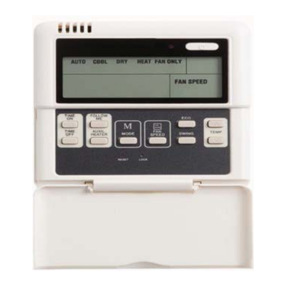
- Page 27 OPERATION AUTO MODE TIMER PERIOD SELECTION PREHEAT OR DEFROST IN PROGRESS SELECTED TEMPERATURE SELF-DIAGNOSTIC CODES Fig. 21 – Unit Display Table 21 – Signal Receiver Functions ION indication lamp(optional function):This lamp illuminates when Clean Air feature is activated. DEFROST indication lamp(For cooling & heating models only): Lights up when the air conditioner starts defrosting automatically or when the warm air control feature is activated in heating operation.
- Page 28 APPENDIX 1 °C °F °C °F °C °F °C °F °C °F 69.8 123.8 179.6 235.4 24.8 71.6 125.6 181.4 237.2 26.6 73.4 127.4 183.2 28.4 75.2 129.2 240.8 30.2 186.8 242.6 25.5 77.9 132.8 188.6 244.4 32.9 78.8 134.6 190.4 246.2 33.8...
Need help?
Do you have a question about the 40MKCB and is the answer not in the manual?
Questions and answers