Carrier Performance 40MBDQ Series Installation Instructions Manual
Ducted slim ductless system
Hide thumbs
Also See for Performance 40MBDQ Series:
- Owner's manual (13 pages) ,
- Owner's manua (12 pages) ,
- Installation instructions manual (26 pages)
Table of Contents
Advertisement
40MBDQ
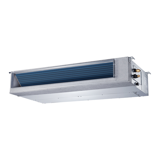
Fig. 1 - Sizes 09K - 48K
NOTE: The 09K-48K unit can be mounted vertically as well as
horizontally.
Fig. 2 - Size 58K
NOTES: Read the entire instruction manual before starting the
installation.
Images are for illustration purposes only. Actual models may
differ slightly.
Installation Instructions
Specifications subject to change without notice.
Ducted Slim Ductless System
TABLE OF CONTENTS
SAFETY CONSIDERATIONS .....................................................................2
INTRODUCTION.........................................................................................3
INSTALLATION REQUIREMENTS.............................................................4
DIMENSIONS..............................................................................................5
INSTALLATION CLEARANCES HORIZONTAL INSTALLATIONS ............7
MAINTENANCE CLEARANCES.................................................................7
INSTALLATION...........................................................................................8
Step 1 - Check Equipment ..........................................................................8
Step 2 - Mount Unit .....................................................................................8
Step 3 - Installing Ductwork.........................................................................10
Step 4 - Condensate Drain Installation........................................................11
Step 5 - Electrical Connections ...................................................................14
WIRING .......................................................................................................15
ELECTRICAL DATA....................................................................................16
CONNECTION DIAGRAMS ........................................................................16
Step 6 - Refrigerant Piping ..........................................................................17
WIRELESS REMOTE CONTROLLER INSTALLATION .............................18
WIRED REMOTE CONTROLLER INSTALLATION....................................18
START−UP .................................................................................................18
Step 7 - Setting Static Pressure or Automatic Airflow .................................19
FAN PERFORMANCES AT VARYING STATIC PRESSURES ..................20
SYSTEM CHECKS......................................................................................28
TROUBLESHOOTING ................................................................................29
ADVANCED SERVICE AND INSTALLATION FUNCTIONS ......................30
Sizes 09 to 58
Advertisement
Table of Contents

Related Manuals for Carrier Performance 40MBDQ Series


Summary of Contents for Carrier Performance 40MBDQ Series
-
Page 1: Table Of Contents
40MBDQ Ducted Slim Ductless System Sizes 09 to 58 Installation Instructions TABLE OF CONTENTS SAFETY CONSIDERATIONS ..............2 INTRODUCTION..................3 INSTALLATION REQUIREMENTS.............4 DIMENSIONS....................5 INSTALLATION CLEARANCES HORIZONTAL INSTALLATIONS ....7 Fig. 1 — Sizes 09K - 48K MAINTENANCE CLEARANCES..............7 NOTE: The 09K-48K unit can be mounted vertically as well as INSTALLATION...................8 horizontally. -
Page 2: Safety Considerations
SAFETY CONSIDERATIONS WARNING Improper installation, adjustment, alteration, service, maintenance, or use can cause explosion, fire, electrical shock, EXPLOSION HAZARD or other conditions which may cause death, personal injury or Failure to follow this warning could property damage. result in death, serious personal injury, Consult a qualified installer, service agency, or your distributor and/or property damage. -
Page 3: Introduction
INTRODUCTION The Ducted Slim models are R-410A fan coils designed with application flexibility in mind. The 9K-48K sizes can be Air inlet mounted horizontally or vertically (upflow) while the 58K size can be mounted only horizontally. A rear and bottom return is available for field modification on Air filter the 9K-48K sizes to match the different applications. -
Page 4: Installation Requirements
INSTALLATION REQUIREMENTS WARNING • Confirm that the ceiling or wall can support the unit’s weight. • Confirm there is enough room within the false ceiling for installation and maintenance. PRODUCT INSTALLATION The false ceiling should be horizontal and leveled. • Installation must be performed by an authorized dealer or specialist. -
Page 5: Dimensions
DIMENSIONS Table 4 — Indoor Unit Dimensions OPERATING AIR OUTLET AIR OUTLET AIR INLET HANGER REFRIGERANT WEIGHT OPENING SIZE OPENING SIZE OPENING SIZE BRACKETS PIPE LOCATIONS LB (KG) Size Unit 27.6 19.9 17.7 21.1 23.6 29.2 14.2 18.1 27.6 19.9 17.7 21.1 23.6... - Page 6 DIMENSIONS (CONT) BOTTOM VIEW REAR VIEW Air Inlet RIGHT VIEW LEFT VIEW TOP VIEW FRONT VIEW Air Outlet NOTE: Size 58K draw-through system Fig. 6 — Indoor Unit Size 58K Specifications subject to change without notice. IM-40MBDQ-05...
-
Page 7: Installation Clearances Horizontal Installations
INSTALLATION CLEARANCES HORIZONTAL INSTALLATIONS > 11.8in(30cm) Strong and durable ceiling >0.8in(2cm) Indoor unit Right Left side side > 0.8in(2cm) Access Panel Ceiling opening size Service access Ceiling > > Ceiling opening size Floor Maintenance space Fig. 7 — Installation Clearances MAINTENANCE CLEARANCES Provide a service access for inspection purposes. -
Page 8: Installation
INSTALLATION Ceiling Mounting Options Different ceiling types call for different mount applications. Step 1 - Check Equipment Wood Unpack the unit and move to the final location. Remove the Place the wood mounting across the roof beam, then install the hanging screw bolts. - Page 9 Provide adequate space for wiring, piping, and servicing of the unit (see “INSTALLATION REQUIREMENTS” on page 4 and “MAINTENANCE CLEARANCES” on page 7). 1. MARK AND DRILL HOLES TO HANG AND INSTALL THE BOLTS Mark the location of the four hanger bolt holes on the ceiling based on the indoor unit’s dimensional drawing.
-
Page 10: Step 3 - Installing Ductwork
RETURN AIR ARRANGEMENT (SIZES 09K-48K ONLY) Step 3 - Installing Ductwork Connect the return and supply air ducts to the ducts over the Based on the return air conditions in the field, the factory configured rear return arrangement of the unit may be modified outside flanges provided on the unit. -
Page 11: Step 4 - Condensate Drain Installation
Step 4 - Condensate Drain Installation Ceiling The condensate pipe is used to drain water away from the unit. Improper installation may cause unit and property damage. The unit is supplied with a drain adapter allowing the use of a field supplied 3/4 in. - Page 12 CONDENSATE DRAIN AND CONDENSATE 3. Sizes 24K, 36K, 48K and 58K have a built-in condensate lift pump. Drain connections (A, B and C) are covered with caps. LIFT PUMP INSTALLATION (HORIZONTAL Connect the drainpipe to connector D (see Fig. 32) INSTALLATION) For sizes 9, 12 and 18, the condensate lift pump is provided in a separate box.
- Page 13 Remove the cap from connector C and connect the condensate During this test, check all bends or joints for leakage. drain pipe to drain connector C (see Fig. 36). NOTE: For size 18K, the external condensate lift pump should be removed (see Fig. 35). Connector C Fig.
-
Page 14: Step 5 - Electrical Connections
Step 5 - Electrical Connections 1. Run a interconnecting wiring from the outdoor unit to the indoor unit. Before proceeding with electrical connections, make certain 2. Connect the wiring from the outdoor unit per the connection that the supply voltage, frequency, phase, and ampacity are as diagram (See Fig. -
Page 15: Wiring
WIRING CAUTION Size all wires per the NEC (National Electrical Code) or CEC (Canadian Electrical Code) and local codes. Use the electrical data from the outdoor unit (MCA - minimum circuit amps and EQUIPMENT DAMAGE HAZARD MOCP - maximum over current protection), to correctly size the wires and the disconnect fuse or breakers respectively. -
Page 16: Electrical Data
ELECTRICAL DATA Table 9 — Electrical Data INDOOR FAN MAX FUSE CB AMP UNIT SIZE V-PH-HZ 1.11 0.18 1.11 0.18 0.27 Refer to outdoor unit installation instructions – Indoor unit powered by the outdoor unit 208-230/1/60 0.27 2.45 0.56 0.75 3.65 0.952 1,000... -
Page 17: Step 6 - Refrigerant Piping
Step 6 - Refrigerant Piping IMPORTANT: Both refrigerant lines must be insulated separately. • The minimum refrigerant line length between the indoor and outdoor units is 10 ft. (3 m). • Table 10 lists the pipe sizes for the indoor unit. Refer to the Indoor unit tubing Flare nut Piping... -
Page 18: Wireless Remote Controller Installation
WIRELESS REMOTE CONTROLLER WIRED REMOTE CONTROLLER INSTALLATION INSTALLATION To connect the included wired remote controller (7 Day Mounting Bracket (if installed on the wall) Programmable KSACN0501AAA) to the indoor unit, the 4-pin adapter cable supplied with the controller and plug it into CN40 1. -
Page 19: Step 7 - Setting Static Pressure Or Automatic Airflow
Step 7 - Setting Static Pressure or Automatic Airflow The indoor ducted units can be programmed for different static CAUTION pressures settings or airflows and the factory default setting is SP1. Use the following steps to set the static pressure or Automatic Airflow using the Wired Remote Controller or the Do not use the AUTOMATIC AIRFLOW ADJUSTMENT with the Wireless Remote Controller according to the installation... -
Page 20: Fan Performances At Varying Static Pressures
FAN PERFORMANCES AT VARYING STATIC PRESSURES Table 13 — Static Pressure at the Rated Point and Static Pressure Range SIZE UNITS STATIC PRESSURE RANGE In. WG 0.068 0.104 0.128 0.176 0~0.20 (0~50) In. WG 0.064 0.10 0.136 0.20 0~0.20 (0~50) In. - Page 21 FAN PERFORMANCES AT VARYING STATIC PRESSURES (CONT.) Air volume m3/h(CFM) Air volume m3/h(CFM 1200(706) 1200(706) 1100(647) 1100(647) 1000(588) 1000(588) 900(529) 900(529) 800(471) 800(471) 700(412) 700(412) 600(353) Rated Point 600(353) Rated point 500(294) 500(294) 400(235) Limit 400(235) 300(176) 300(176) Limit 200(118) 200(118) 100(59) 100(59)
- Page 22 FAN PERFORMANCES AT VARYING STATIC PRESSURES (CONT.) Air volume m3/h(CFM) Air volume m3/h(CFM) 1200(706) 1200(706) 1100(647) 1100(647) 1000(588) 1000(588) 900(529) 900(529) 800(471) 800(471) 700(412) 700(412) Rated point Rated point 600(353) 600(353) Limit 500(294) 500(294) 400(235) 400(235) Limit 300(176) 300(176) 200(118) 200(118) 100(59) 100(59)
- Page 23 FAN PERFORMANCES AT VARYING STATIC PRESSURES (CONT.) Air volume m3h(CFM) Air volume m3h(CFM) 1800(1059) 1800(1059) 1700(1000) 1700(1000) 1600(941) 1600(941) 1500(882) 1500(882) 1400(823) 1400(823) 1300(765) 1300(765) Limit 1200(706) Limit 1200(706) 1100(647) 1100(647) 1000(588) 1000(588) Rated point Rated point 900(529) 900(529) 800(471) 800(471) High 700(412)
- Page 24 FAN PERFORMANCES AT VARYING STATIC PRESSURES (CONT.) Fig. 58 — Fan Performance - Size 24 Specifications subject to change without notice. IM-40MBDQ-05...
- Page 25 FAN PERFORMANCES AT VARYING STATIC PRESSURES (CONT.) Air volume m3h(CFM) Air volume m3h(CFM) 3600(2118) 3600(2118) 3400(2000) 3400(2000) 3200(1882) 3200(1882) 3000(1765) 3000(1765) 2800(1647) 2800(1647) 2600(1529) 2600(1529) 2500(1471) 2500(1471) 2400(1412) 2400(1412) 2200(1294) 2200(1294) 2000(1176) 2000(1176) Rated point Rated point 1800(1059) 1800(1059) 1600(941) 1600(941) Limit 1400(823)
- Page 26 FAN PERFORMANCES AT VARYING STATIC PRESSURES (CONT.) Air volume m3h(CFM) Air volume m3h(CFM) SP2 4200(2471) 4200(2471) 4000(2353) 4000(2353) 3800(2235) 3800(2235) 3600(2118) 3600(2118) 3400(2000) 3400(2000) 3200(1882) 3200(1882) 3100(1824) 3100(1824) 3000(1765) 3000(1765) 2800(1647) 2800(1647) 2600(1529) Rated point 2600(1529) 2400(1412) Rated point Limit 2400(1412) 2200(1294) 2200(1294)
- Page 27 FAN PERFORMANCES AT VARYING STATIC PRESSURES (CONT.) Air volume m3h(CFM) Air volume m3h(CFM) 4600(2706) 4600(2706) 4400(2588) 4400(2588) 4200(2471) 4200(2471) 4000(2353) 4000(2353) 3800(2235) 3800(2235) 3600(2118) 3600(2118) 3400(2000) 3400(2000) 3200(1882) 3200(1882) Rated point 3000(1765) Rated point 3000(1765) 2800(1647) 2800(1647) 2600(1529) 2600(1529) 2400(1412) 2400(1412) 2200(1294) Limit...
-
Page 28: System Checks
SYSTEM CHECKS Size 58K: Two methods available: 1. Conceal the tubing where possible. 2. Ensure the drain tube slopes downward along its entire length. 1. Remove the front side plate from the top. 3. Ensure all tubing and connections are properly insulated. Remove the top cover. -
Page 29: Troubleshooting
TROUBLESHOOTING For ease of service, the systems are equipped with diagnostic code display LEDs on both the indoor and outdoor units. The outdoor diagnostic display consists of two LEDs (red and green) on the outdoor unit board and is limited to a few errors. The indoor diagnostic display is a combination of flashing LEDs on the display panel or the front of the unit. -
Page 30: Advanced Service And Installation Functions
ADVANCED SERVICE AND INSTALLATION FUNCTIONS Refer to the Wireless Remote Controller service manual for access to advanced functions such as: • Auto-Start • Temperature Compensation • Filter Reminder • Indoor Fan Motor Speed Control (after set temperature is reached) • Lowest or Highest Temperature Setting •...
Need help?
Do you have a question about the Performance 40MBDQ Series and is the answer not in the manual?
Questions and answers