Table of Contents
Advertisement
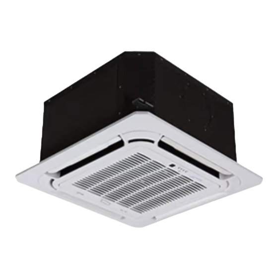
40MKCC / 24AHA4 / 124ANS
40MKQC / 25HHA4 / 224ANS
Cassette Ductless Split System
Sizes 18 to 34
TABLE OF CONTENTS
. . . . . . . . . . . . . . . . . . . . . . . . . . . . . . . . . . .
. . . . . . . . . . . . . . . . . . . . . . . . . . . . . . . . . .
. . . . . . . . . . . . . . . . . . . . . . . . . . . . . . . . . . . . . .
. . . . . . . . . . . . . . . . . . . . . . . . . . . . . . . . . . . . .
. . . . . . . . . . . . . . . . . . . . . . . . . . . . . . . .
. . . . . . . . . . . . . . . . . . . . . . . . . . . . .
. . . . . . . . . . . . . . . . . . . . . . . . . . . . . .
. . . . . . . . . . . . . . . . . . . . . . . . . . . . . . . . . . . .
. . . . . . . . . . . . . . . . . . . . . . . . . . . . . . . . . . . . . . .
SAFETY CONSIDERATIONS
Installing, starting up, and servicing air- -conditioning equipment
can be hazardous due to system pressures, electrical components,
and equipment location (roofs, elevated structures, etc.).
Only trained, qualified installers and service mechanics should
install, start- -up, and service this equipment.
Untrained personnel can perform basic maintenance functions such
as cleaning coils. All other operations should be performed by
trained service personnel.
When working on the equipment, observe precautions in the
literature and on tags, stickers, and labels attached to the
equipment.
Follow all safety codes. Wear safety glasses and work gloves. Keep
quenching cloth and fire extinguisher nearby when brazing. Use
care in handling, rigging, and setting bulky equipment.
Read this manual thoroughly and follow all warnings or cautions
included in literature and attached to the unit. Consult local
building codes and National Electrical Code (NEC) for special
requirements. Recognize safety information. This is the safety- -alert
symbol
! !
. When you see this symbol on the unit and in
instructions or manuals, be alert to the potential for personal injury.
Understand these signal words: DANGER, WARNING, and
CAUTION. These words are used with the safety- -alert symbol.
DANGER identifies the most serious hazards which will result in
severe personal injury or death. WARNING signifies hazards
which could result in personal injury or death. CAUTION is used
to identify unsafe practices which may result in minor personal
injury or product and property damage. NOTE is used to highlight
suggestions which will result in enhanced installation, reliability, or
operation.
Service Manual
PAGE
. . . . . . . . . . . . . . . . . . . . . . . . .
. . . . . . . .
. . . . . . . . . . .
. . . . . . . . . . . . . . . .
. . . . . . . . . . . . . . . . . . . . . . . . .
. . . . . . . . . . . . . . . .
. . . . . . . . . . . . .
. . . . . . . . . . . . . . . . . . . . . . . .
!
1
ELECTRICAL SHOCK HAZARD
1
Failure to follow this warning could result in personal
2
injury or death.
3
Before installing, modifying, or servicing system, main
4
electrical disconnect switch must be in the OFF
6
position. There may be more than 1 disconnect switch.
8
Lock out and tag switch with a suitable warning label.
9
10
!
11
16
17
17
18
19
23
29
!
EQUIPMENT DAMAGE HAZARD
Failure to follow this caution may result in equipment
damage or improper operation.
Do not bury more than 36 in. (914 mm) of refrigerant pipe
in the ground. If any section of pipe is buried, there must be
a 6 in. (152 mm) vertical rise to the valve connections on
the outdoor units. If more than the recommended length is
buried, refrigerant may migrate to the cooler buried section
during extended periods of system shutdown. This causes
refrigerant slugging and could possibly damage the
compressor at start- -up.
INTRODUCTION
This Service Manual provides the necessary information to service,
repair, and maintain the MK family of air conditioners and heat
pumps. Section 2 of this manual is an appendix with data required
to perform troubleshooting. Use the Table of Contents to locate a
desired topic.
WARNING
WARNING
EXPLOSION HAZARD
Failure to follow this warning could
result in death, serious personal injury,
and/or property damage.
Never use air or gases containing
oxygen for leak testing or operating
refrigerant compressors. Pressurized
mixtures of air or gases containing
oxygen can lead to an explosion.
CAUTION
Advertisement
Table of Contents

Related Manuals for Carrier 40MKCC


Summary of Contents for Carrier 40MKCC
-
Page 1: Table Of Contents
40MKCC / 24AHA4 / 124ANS 40MKQC / 25HHA4 / 224ANS Cassette Ductless Split System Sizes 18 to 34 Service Manual TABLE OF CONTENTS WARNING PAGE SAFETY CONSIDERATIONS ...... -
Page 2: Model / Serial Number Nomenclatures
MODEL / SERIAL NUMBER NOMENCLATURES INDOOR UNIT --- --- 40= FAN COIL UNIT VOLTAGE 3 = 208/230 ---1 ---60 MK = MODEL SYSTEM TYPE C = COOLING ONLY Q = HEAT PUMP MAXIMUM NUMBER OF FAN COIL UNITS THAT CAN BE CONNECTED TO THE OUTDOOR UNIT NOT USED B=1:1 NOMINAL CAPACITY... -
Page 3: Standard Features And Accessories
STANDARD FEATURES AND ACCESSORIES ACCESSORIES Table 1—Standard Features Ease Of Installation Table 2—Accessories Indoor and Outdoor Compact Size Ordering No. Description For Models Outdoor Unit Wall Mounting Kit KSACN0101AAA Wired Remote Control All Sizes Outdoor Unit Stacking Kit 40MK- -B01C- -- -3 Grille/Ceiling panel Cassette Indoor units Indoor Mounting Bracket... -
Page 4: Specifications
SPECIFICATIONS Table 3—Cooling Only COOLING ONLY Size 24AHA418A003 24AHA424A003 24AHA430A003 24AHA436A003 24AHA436A005 24AHA436A006 Outdoor Model 124ANS018000 124ANS024000 124ANS030000 124ANS036000 124APS036000 124AES036000 System Indoor Model 40MKCB18C- -- -3 40MKCB34C- -- -3 40MKCB34C- -- -3 40MKCB34C- -- -3 40MKCB34C- -- -3 40MKCB34C- -- -3 Energy Star Cooling Rated Capacity Btu/h... - Page 5 SPECIFICATIONS (CONT) Table 4—Heat Pump HEAT PUMP Size 25HHA424A003 25HHA430A003 25HHA436A003 25HHA436A005 25HHA436A006 Outdoor Model 224ANS030000 224ANS036000 224APS036000 224AES036000 224ANS048000 System Indoor Model 40MKQB34C--3 40MKQB34C--3 40MKQB34C--3 40MKQB34C--3 40MKQB34C--3 Energy Star Cooling Rated Capacity Btu/h 23,400 28,400 32,600 32,600 32,600 SEER 11.2 12.2 12.2...
-
Page 6: Dimensions
DIMENSIONS - - INDOOR Cassette Grille Cassette Body Drain pipe Refrigerant pipe connector connector Fresh air intake ( Φ75mm) A150291 Fig. 2 – 40MKC**C, 40MKQ**C Unit and Panel Dimensions Table 5—Dimensions Indoor Indoor Unit Size Height (H) Width (W) Depth (D) Operating Weight BTU/Hr in (mm) - Page 7 DIMENSIONS - - OUTDOOR Fig. 3 – Outdoor Unit Dimensions Table 6—Dimensions Outdoor OPERATING Dimensions in (mm) WEIGHT UNIT Ibs (kg) 31.1 36.9 14.6 23.4 17.2 23.1 28.1 11.3 24AHA418 (791) (938) (370) (406) (595) (437) (587) (713) (330) (168) (286) (16) (73)
-
Page 8: Clearances
CLEARANCES - - INDOOR A150152 Fig. 4 – 40MKC**C, 40MKQ**C Unit Clearance CLEARANCES - - OUTDOOR Air-outlet Air-inlet A08436 Fig. 5 – Outdoor Unit Clearance Table 7—Clearances Indoor UNIT Coil Facing Wall - - in. (mm) Fan Facing Wall - - in. (mm) 24 (610) 24 (610) 24 (610) -
Page 9: Electrical Data
ELECTRICAL DATA Table 8—24AHA4/124ANS Electrical Data MAX FUSE** OPER VOLTS* COMP Unit Size - - V/PH or CKT BRK voltage series AMPS 18- -30 56.3 0.50 11.8 24- -30 62.9 10.9 0.50 14.1 208/230/1 30- -30 73.0 14.1 0.70 18.3 36- -30 77.0 14.1... -
Page 10: Power And Connecting Cables
POWER AND CONNECTING CAUTION CABLES - - FIELD SUPPLIED Recommended Connection Method for Power and EQUIPMENT DAMAGE HAZARD Communication Wiring (To minimize Failure to follow this caution may result in equipment damage or improper operation. communication wiring interference) S Wires should be sized based on NEC and local codes. Power Wiring: S Use copper conductors only with a 600 volt rating and The main power is supplied to both, the indoor and the outdoor... -
Page 11: Connection Diagrams
CONNECTION DIAGRAMS A150280 Fig. 6 – 40MKCB**C/24AHA4 or 124ANS Connecting Diagram A150282 Fig. 7 – 40MKQB**C/25HHA4 or 224ANS Connecting Diagram Notes: 1. Do not use thermostat wire for any connection between indoor and outdoor units. 2. All connections between indoor and outdoor units must be as shown. The connections are sensitive to polarity and will result in a fault code. - Page 12 JR 6 Legend: ....Model sp ecific fe ature To C C M C omm.B us CN 1: Live wire L1/Null line L2 CN 17: Null line C CN111 :Comp ressor si gnal CN 8: Fa n interface CN 6: Co nnectors interface JR 6 CN 23...
- Page 13 Fig. 10 – 24AHA4/124ANS Wiring Diagram 208/230 - - 460V 3 Phase JR 6 Legend: ....Model sp ecific fea ture To C C M C omm.B us CN 1: Live wire L1/Null l ine L2 CN 17: Controls 24V sign al interfac e(R/C) CN111 : Signal in terface(Y /O) CN 8:New fan...
- Page 14 OUTDOOR UNIT SCHEMATIC DIAGRAM Fig. 12 – 25HHA4/224ANS Wiring Diagram 208/230V 1 Phase Fig. 13 – 25HHA4/224ANS Wiring Diagram 208/230V 3 Phase...
- Page 15 Fig. 14 – 25HHA4/224ANS Wiring Diagram 460V 3 Phase...
-
Page 16: Refrigeration Cycle Diagrams
REFRIGERATION CYCLE DIAGRAMS FIELD PIPING FLARE CONNECTION LIQUID COOLING EXPANSION SERVICE VALVE DEVICE HEAT HEAT EXCHANGER EXCHANGER (EVAPORATOR) (CONDENSER) SERVICE VALVE W/GAUGE PORT SUCTION LINE FLARE CONNECTION COMPRESSOR FIELD PIPING Fig. 15 – Cooling Only FIELD PIPING FLARE CONNECTION LIQUID TWO PHASE COOLING LIQUID HTG... -
Page 17: Refrigerant Lines
REFRIGERANT LINES Metering Device The 40MKC(Q)*C unit uses a TXV while the outdoor unit uses a General refrigerant line sizing: type B accurator. The cooling metering device is installed with the 1 The outdoor units are shipped with a full charge of R410A indoor unit. -
Page 18: Sequence Of Operation
EVACUATE Manifold Gage BREAK VACUUM WITH DRY NITROGEN WAIT 500 microns Low side valve High side valve EVACUATE Charge hose Charge hose BREAK VACUUM WITH DRY NITROGEN Vacuum pump WAIT EVACUATE CHECK FOR TIGHT, DRY SYSTEM Low side valve (IF IT HOLDS DEEP VACUUM) A07361 Fig. -
Page 19: Troubleshooting
TROUBLESHOOTING For ease of service, the indoor unit is equipped with diagnostic code display LEDs in the indoor units. This diagnostic display is a This section provides the required flow charts to troubleshoot combination of flashing LEDs on the display panel or the front of problems that may arise. - Page 20 1 --- Open or short circuit of T1 or T2 temperature sensor --- diagnosis and solution Error Code Malfunction conditions Indoor room temperature T1 and sensor evaporator temperature sensor T2 is abnormal Check the connec ons Check the connec ons between temperature between temperature Correct the connec ons.
- Page 21 2 --- EEPROM parameter error --- diagnosis and solution Error Code Malfunction conditions Indoor PCB main chip does not receive feedback from EEPROM chip. • Installation mistake Possible Causes • Defective PCB Troubleshooting: Shut off the power supply and turn it on 5 seconds later. Is it still displaying the error code? If the EEPROM chip is welded on main...
- Page 22 3 --- Water ---level alarm --- diagnosis and solution Error Code Malfunction conditions If the sampling voltage is not 5V, the LED displays the failure. • Wiring mistake • Water--- level switch faulty Possible Causes • Water pump faulty • Indoor PCB faulty Power off, then restart the unit 2 minutes Power off, then restart the unit 2 minutes later.
-
Page 23: Disassembly
DISASSEMBLY OF CASSETTE INDOOR UNIT All the operations should be performed after powered off. Parts name Procedures Remarks Remove the 1) Open the grill filter Use two fingers to press the clips on the grille (pic.1), then hitch the grille and open it (pic.2, pic.3) Pic.1 Pic.2... - Page 24 Remove the 1) Open the grill Repeat the operation of step1 of No. 1 display 2) Remove the grill Repeat the operation of step2 of No. 1 board In order to prevent the grille falling down, it’s necessary to remove it. 3) Disassemble the display board Remove the two screws...
- Page 25 4) Remove the PCB from the fixing pins. There are white lines on the PCB to show the position of the pins. Fixing pin Remove the 1) Open the grill Repeat the operation of step1 of No.1(No need electronic to take down the panel) control box 2) Remove the electronic Repeat the operation of step 2 of No.3...
- Page 26 Remove the 1) Open the grill Repeat the operation of step1 of No.1(No need volute shell to take down the panel) 2) Remove the electronic Repeat the operation of No.4 control box 3) Screw off the 3 screws to remove the volute shell 3 screws Remover 1) Repeat the operation of...
- Page 27 3) Remove the 3 nuts to disassemble the fan motor 3 nuts Remove the 1) Remove the panel Repeat the operation of No.5 water 2) Remove the electronic Repeat the operation of No.4 collector control box assembly 3) Remove the volute shell Repeat the operation of No.6 4) Screw off the screws to remove the water...
- Page 28 4) Screw off the screws to remove the drain pump 3 screws 5) Take out the drain pump Remove the 1) Remove the water Repeat the operation of No.9 evaporator collector assembly 2) Remove the seal board of evaporator Two screws 3) Remove the evaporator fixing board Six screws...
-
Page 29: Appendix
APPENDIX APPENDIX TABLE OF CONTENTS DESCRIPTION NUMBER Control Board Input/Output Values ............... Temperature Sensor Values (Temperature vs. - Page 30 Table 19 – Temperature Sensor Resistance Value Table for T1, T2, T3, T4 K Ohm K Ohm K Ohm K Ohm - - 20 - - 4 115.266 12.6431 2.35774 0.62973 - - 19 - - 2 108.146 12.0561 2.27249 0.61148 - - 18 101.517...
- Page 31 Table 20 – Temperature Sensor Resistance Value Table for T5 K Ohm K Ohm K Ohm K Ohm - - 20 - - 4 542.7 68.66 13.59 3.702 - - 19 - - 2 511.9 65.62 13.11 3.595 - - 18 62.73 12.65 3.492...
- Page 32 A4 Display Panel Function indicators on indoor unit display panel Alarm indicator DEF./FAN lamp Flashes when a failure is detected Illuminates during DEFROST operation Manual button Timer indicator Service purpose switch - to be Illuminates during TIMER operation MANUAL used by trained personnel only Infrared signal receiver Receives the signal from remote Temperature indicator...
- Page 33 Table 21 – Temperature Conversion °C °F °C °F °C °F °C °F °C °F 69.8 123.8 179.6 235.4 24.8 71.6 125.6 181.4 237.2 26.6 73.4 127.4 183.2 28.4 75.2 129.2 240.8 30.2 186.8 242.6 25.5 77.9 132.8 188.6 244.4 32.9 78.8 134.6...
- Page 34 Catalog No.40MKC(Q)B---C ---01SM Copyright 2015 CAC/BDP . S 7310 W. Morris St. S Indianapolis, IN 46231 Edition Date: 09/15 Replaces: New Manufacturer reserves the right to change, at any time, specifications and designs without notice and without obligations.
Need help?
Do you have a question about the 40MKCC and is the answer not in the manual?
Questions and answers