
Related Manuals for klover DIVA


Summary of Contents for klover DIVA
- Page 1 IDRO FIRMWARE with LED display Installed on: STAR 14 – STAR 14 Sartoriale DIVA DIVA MID DIVA PLUS MAGNIFIKA PELLET FIRE PLACE 18 BI-FIRE MID BI-FIRE TECHNICAL MANUAL Updated on 02/07/13 – Rev. 2.5...
-
Page 3: Table Of Contents
TABLE OF CONTENTS GENERAL DESCRIPTION ............................4 Console ..................................4 What are the buttons for ............................6 THE MENU - CHRONO-THERMOSTAT ........................7 OPERATIVE MODE ..............................8 Stove ignition................................8 No stove ignition................................ 9 Stove working................................9 Modification of DHW and water temperature setting ....................9 TEMPERATURE PROBES ............................ -
Page 4: General Description
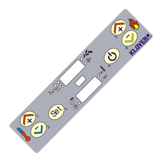
GENERAL DESCRIPTION Console The equipment's functioning state is displayed by the console. Many types of displays and the available settings based on the selected menu can be made by accessing the menu. Figure 1 shows the display in equipment on conditions. WORK POWER °C Po 5... - Page 5 Figure 4 describes the meaning of the state LEDs on the display's console (1st LED SERIES). CHRONO-THERMOSTAT: the LED is on when at least one ignition and switch-off program is active. °C ROOM THERMOSTAT: the LED is on when room thermostat contact is open. IGNITION RESISTANCE: the LED is on when ignition resistance is active.
-
Page 6: What Are The Buttons For
What are the buttons for BUTTON DESCRIPTION MODE ACTION In programming.. Modifies/increases the selected menu value. Increases temperature (1) Working/off (after having Increases DHW/water thermostat pressed SET once). temperature value. Modifies/decreases the selected menu In programming.. value. Decreases temperature (2) Working/off (after having Decreases DHW/water thermostat pressed SET once). -
Page 7: The Menu - Chrono-Thermostat
THE MENU - CHRONO-THERMOSTAT The Menu is accessed by pressing key 3 (Set) twice. This is divided into different levels (called UT...) to access the board's programming and settings. The technical programming access menu entry (UT04) (parameters reserved to Technical Assistance Centre) (see “Power board calibrations”). -
Page 8: Operative Mode
OPERATIVE MODE The stove's normal functioning principle with reference to the available functions for the user is described below. The display appears as in figure 6 before igniting the stove. STOVE STATE °C 22:35 Fig. 6 CLOCK Stove ignition Press key 4 for a few seconds to ignite the stove. Ignition is shown on display as in figure °C Fig. -
Page 9: No Stove Ignition
Devices Flue gas Ignition Country Duration intake Screw feed Pump When it occurs resistance device ON/OFF 8” FUN ASP For the first 8" in ignition For a time set on Pr01 or before reaching LOAD PELL Pr01 temperature on Pr13 after “FUN ASP” state For a time set on Pr02 after “LOAD PELL”... -
Page 10: Temperature Probes
The stove enters functioning economy upon reaching said temperature. The stove now automatically switches off if at least one of the following conditions exist: If it remains in Functioning Economy “ECO-H2O” for a time set on Pr23 (120 minute default setting). ... -
Page 11: Pellet Flue Gas Temperature Probe
Pellet flue gas temperature probe The flue gas probe used to measure the pellet's flue gas temperature has the following features: Thermocouple probe: J type Measuring field: 0/+350°C Obtain a tester to check if probe is faulty, set it in ohm and measure the two probe pins (wire ends); however, this only verifies if the probe is interrupted (no change compared to value shown on unconnected tester). -
Page 12: What Happens If
WHAT HAPPENS IF..the stove does not ignite In case of no ignition, the “NO FIRE” alarm is displayed. Hold button 4 (switch on/off) for a few seconds to restore the stove to standard conditions (remove the alarm)..lack of power for a few seconds Once the power is restored, the stove immediately restarts from the status it had before the power outage (recovering the set work power). -
Page 13: Functioning Principle
FUNCTIONING PRINCIPLE Ignition cycle The ignition cycle can last max 18 minutes and is divided into three phases: 1 - FUN ASP Intake device function duration 8 seconds 2 - LOAD PELL Pellet loading and resistance ignition Pr01 = “LOAD PELL” duration A pre-load phase may be present in “LOAD PELL”... -
Page 15: Work Phase
Work phase The set work power or 1, 2, 3, 4, 5, SANI (optional) is shown on upper display during the stove's normal functioning. A “SET H20” (maximum temperature) can be set by working from Power 1 to Power 5. The stove enters Functioning Economy “ECO-H2O”... -
Page 17: Dhw Power Work Phase
DHW power work phase The domestic hot water is produced instantly via a double heat exchanger immersed in the water inside the stove. Therefore, the stove must be at temperature (60°C at least) to have domestic hot water. Set stove in DHW power “SANI” if a large amount of domestic hot water is required. The DHW power function “SANI”... -
Page 19: Work Phase With Open Room Thermostat Contact
Work phase with open room thermostat contact A bridge clamp is found at back of stove for connecting a room thermostat. OPERATION PRINCIPLE With open contact: 1. The stove passes directly to the “ECO TOFF” operation economy mode. 2. The stove pump switches off. 3. -
Page 21: Bi-Fire Mid And Bi-Fire Functioning Principle
BI-FIRE MID and BI-FIRE Functioning principle The stove can function just with pellets, just with wood or with both combustion chambers on. There are two functioning conditions: Pellet side conditions with “PELL ON”: it switches on automatically when the wood side switches off; ... -
Page 22: Bootloader Programmer
BOOTLOADER PROGRAMMER Firmware loading in power board The following must be executed without USB connection. Use the microswitches to select the firmware to be installed in the board. Connect the BootLoader to the unpowered board using only the supplied serial cable. Power the board and see that the green LED flashes (if not, repeat operation) and the red... -
Page 23: Database
“Parameters tables” to see the default settings). REFERENCE VALUE “Database” setting key (default settings) DIVA “Database” setting key (default settings) STAR 14 “Database” setting key (default settings) DIVA MID “Database” setting key (default settings) DIVA PLUS “Database” setting key (default settings) MAGNIFIKA “Database”... -
Page 24: Power Board Calibrations
10. POWER BOARD CALIBRATIONS N.B. The following description is reserved to the Authorised Technical Assistance Centre with specific product competence. Haphazardly modifying parameters can seriously damage the equipment, persons and the environment. 10.1 Calibrations access keys reserved to T.A.C. table The access keys in the table allow access to all that is reserved to Technical Assistance Centre accessing from UT04 menu (menu reserved to TAC). -
Page 25: How To Calibrate Pellet Flue Gas Probe
10.3 How to calibrate pellet flue gas probe Follow the procedure below to calibrate the flue gas temperature probe: Press SET (no. 3) 5 times. °C Ut 04 S.R.L. Set code "F9" in lower display using “temperature increase/decrease” keys (no. 1 or 2). Press SET (no. -
Page 26: Parameters Tables
11. PARAMETERS TABLES All parameters tables with database entered via access key are shown below. Depending on flue draught, the parameters in red must be checked and eventually modified upon Commissioning. DIVA FIRMWARE (DV130710_3.ENC) GENERAL PARAMETERS ACCESS KEY A9 Parameter Description Measurement Value field... - Page 27 STAR14 FIRMWARE (DV130710_3.ENC) GENERAL PARAMETERS ACCESS KEY A9 Parameter Description Measurement Value field Database P0 Ignition cycle maximum time “LOAD PELL” 1 – 18 Pr01 Minutes Start time “FIRE ON” 1 – 15 Pr02 Minutes 2 – 255 Pr03 Time interval between the two brazier cleaning operations Minutes Screw feed motor reducer ON time in ignition phase “LOAD PELL”...
- Page 28 DIVA MID FIRMWARE (DVP070513_6.ENC) GENERAL PARAMETERS ACCESS KEY A9 Parameter Description Measurement Value field Database P0 Ignition cycle maximum time “LOAD PELL” 1 – 18 Pr01 Minutes Start time “FIRE ON” 1 – 15 Pr02 Minutes 2 – 255 Pr03 Time interval between the two brazier cleaning operations Minutes Screw feed motor reducer ON time in ignition phase “LOAD PELL”...
- Page 29 DIVA PLUS FIRMWARE (DVP070513_6.ENC) GENERAL PARAMETERS ACCESS KEY A9 Parameter Description Measurement Value field Database o0 Ignition cycle maximum time “LOAD PELL” 1 – 18 Pr01 Minutes Start time “FIRE ON” 1 – 15 Pr02 Minutes 2 – 255 Pr03 Time interval between the two brazier cleaning operations Minutes Screw feed motor reducer ON time in ignition phase “LOAD PELL”...
- Page 30 MAGNIFIKA FIRMWARE (MP070509_2.ENC) GENERAL PARAMETERS ACCESS KEY A9 Parameter Description Measurement Value field Database o0 Ignition cycle maximum time “LOAD PELL” 1 – 18 Pr01 Minutes Start time “FIRE ON” 1 – 15 Pr02 Minutes 2 – 255 Pr03 Time interval between the two brazier cleaning operations Minutes Screw feed motor reducer ON time in ignition phase “LOAD PELL”...
- Page 31 PELLET FIRE PLACE 18 FIRMWARE (PFP100709_3.ENC) GENERAL PARAMETERS ACCESS KEY A9 Parameter Description Measurement Value field Database o0 Ignition cycle maximum time “LOAD PELL” 1 – 18 Pr01 Minutes Start time “FIRE ON” 1 – 15 Pr02 Minutes 2 – 255 Pr03 Time interval between the two brazier cleaning operations Minutes...
- Page 32 BI-FIRE MID FIRMWARE (BF131211_6.ENC) GENERAL PARAMETERS ACCESS KEY A9 Parameter Description Measurement Value field Database P0 Ignition cycle maximum time “LOAD PELL” 1 – 18 Pr01 Minutes Start time “FIRE ON” 1 – 15 Pr02 Minutes 2 – 240 Pr03 Time interval between the two brazier cleaning operations Minutes Screw feed motor reducer ON time in ignition phase “LOAD PELL”...
- Page 33 BI-FIRE FIRMWARE (BF131211_6.ENC) GENERAL PARAMETERS ACCESS KEY A9 Parameter Description Measurement Value field Database o0 Ignition cycle maximum time “LOAD PELL” 1 – 18 Pr01 Minutes Start time “FIRE ON” 1 – 15 Pr02 Minutes 2 – 240 Pr03 Time interval between the two brazier cleaning operations Minutes Screw feed motor reducer ON time in ignition phase “LOAD PELL”...
-
Page 34: Parameters Explanation
12. PARAMETERS EXPLANATION Ignition cycle maximum time “LOAD PELL” Pr01 Allows setting maximum time granted for ignition phase. The flue gas temperature set on Pr13 must be reached within the limit time set in this parameter to change to work phase. if sufficient flue gas temperature (Pr13) is reached change to work phase is immediate, therefore we recommend keeping this parameter set at maximum value 18' (default setting). - Page 35 Temperature differential on “SET H2O” and “SET SANI” for switch-off/on Pr12 Allows setting temperature differential on “SET H2O” and “SET SANI” for equipment switch-off and re-ignition. The equipment automatically switches off placing itself in “STOP FIRE” stand-by position once the temperature differential (or “SET H2O”...
- Page 36 Pr21 Flue gas intake speed in power 4 work phase Allows setting flue gas intake device speed when equipment is working in POWER 4. If using a difficult to burn "hard" (or dark) pellet, this parameter value can be increased. The same must also be increased/decreased depending on flue draught.
- Page 37 after time set on parameter Pr27. Pay attention as the three-way valve exchange temperature also varies when varying "SET SANI" temperature. Example: WORK POWER: SANI SET SANI = 70°C Pr26 = 10°C Pr27 = 60” The valve opens in pellet thermo stove DHW circuit after 60" from reaching 61°C. It closes after 60"...
- Page 38 Pr55 Time for pellet side switch-on if the conditions exist after wood side switch-off Allows setting the time (minutes) after which the pellet side automatically switches on following wood side (see “BI-FIRE MID and BI-FIRE Functioning principle”). This parameter can be increased or switch-off decreased if necessary to anticipate or delay pellet side ignition.
-
Page 39: Wiring Diagrams
13. WIRING DIAGRAMS 13.1 DIVA – STAR14 wiring diagram (Motherboard I023) EARTH BOARD I023 FUSE 4A 5X20 TRANSFORMER PHASE 230Vac NEUTRAL NETWORK FLUE GAS EXTRATION INTAKE DEVICE DISSIPATER SCREW FEED MOTOR REDUCER IGNITION RELAY IGNITION RESISTANCE DISPLAY CONNECTOR BROWN CR2032 3Volts HEATING SYSTEM CHRONO-THERMOSTAT PUMP... -
Page 40: Diva Mid - Diva Plus Wiring Diagram (Motherboard I023)
13.2 DIVA MID – DIVA PLUS wiring diagram (Motherboard I023) EXPANSION BOARD I055 New serial connection FOR 3-WAY VALVE (OPTIONAL) EXPANSION BOARD I055 CONNECTED TO I023 WITH CONNECTORS CN10 AND CN12 connector to CN13 EARTH on board I023 BOARD I023 FUSE FUSE 3,15A 5X20... -
Page 41: Magnifika Wiring Diagram (Motherboard I023)
13.3 MAGNIFIKA wiring diagram (Motherboard I023) 4 x 0,75 CABLE (OPTIONAL) FOR CONNECTION OF THE MOTORISED 3-WAY VALVE GREEN/YELLOW EARTH ON CALBE EARTH BROWN ON CABLE BOARD I023 FUSE 4A 5X20 TRANSFORMER PHASE 230Vac NEUTRAL NETWORK FLUE GAS EXTRATION INTAKE DEVICE BLACK ON CABLE BLUE ON CABLE DISSIPATER... -
Page 42: Pellet Fire Place 18 Wiring Diagram (Motherboard I023)
13.4 PELLET FIRE PLACE 18 wiring diagram (Motherboard I023) EARTH BOARD I023 FUSE 4A 5X20 TRANSFORMER PHASE 230Vac NEUTRAL NETWORK FLUE GAS EXTRATION INTAKE DEVICE DISSIPATER SCREW FEED MOTOR REDUCER IGNITION RELAY IGNITION RESISTANCE DISPLAY CONNECTOR BROWN CR2032 3Volts HEATING SYSTEM CHRONO-THERMOSTAT PUMP CLOCK BATTERY... -
Page 43: Bi-Fire Mid - Bi-Fire Wiring Diagram (Motherboard I023)
13.5 BI-FIRE MID – BI-FIRE wiring diagram (Motherboard I023) EXPANSION BOARD I055 New serial connection FOR 3-WAY VALVE (OPTIONAL) EXPANSION BOARD I055 CONNECTED TO I023 WITH CONNECTORS CN10 AND CN12 RECIRCULATION PUMP connector to CN13 EARTH on board I023 BOARD I023 FUSE FUSE 3,15A 5X20... -
Page 44: Useful Advice
14. USEFUL ADVICE Anticipate change to work phase without having to wait entire ignition cycle. Keep key 5 pressed (power increase) to go directly to work phase without waiting for stove to perform the entire ignition cycle. The flue gas must have reached minimum temperature to consider stove on (Pr13), to go onto work phase. -
Page 45: Notes
15. NOTES ________________________________________________________________________________ ________________________________________________________________________________ ________________________________________________________________________________ ________________________________________________________________________________ ________________________________________________________________________________ ________________________________________________________________________________ ________________________________________________________________________________ ________________________________________________________________________________ ________________________________________________________________________________ ________________________________________________________________________________ ________________________________________________________________________________ ________________________________________________________________________________ ________________________________________________________________________________ ________________________________________________________________________________ ________________________________________________________________________________ ________________________________________________________________________________ ________________________________________________________________________________ ________________________________________________________________________________ ________________________________________________________________________________ ________________________________________________________________________________ ________________________________________________________________________________ ________________________________________________________________________________ ________________________________________________________________________________ ________________________________________________________________________________... - Page 46 ________________________________________________________________________________ ________________________________________________________________________________ ________________________________________________________________________________ ________________________________________________________________________________ ________________________________________________________________________________ ________________________________________________________________________________ ________________________________________________________________________________ ________________________________________________________________________________ ________________________________________________________________________________ ________________________________________________________________________________ ________________________________________________________________________________ ________________________________________________________________________________ ________________________________________________________________________________ ________________________________________________________________________________ ________________________________________________________________________________ ________________________________________________________________________________ ________________________________________________________________________________ ________________________________________________________________________________ ________________________________________________________________________________ ________________________________________________________________________________ ________________________________________________________________________________ ________________________________________________________________________________ ________________________________________________________________________________ ________________________________________________________________________________ ________________________________________________________________________________...
- Page 48 Via A. Volta, 8 37047 San Bonifacio (VR) Tel: 045 6101859 Fax: 045 6101858 e-mail: klover@klover.it internet: www.klover.it...
Need help?
Do you have a question about the DIVA and is the answer not in the manual?
Questions and answers