
Related Manuals for klover DEA ECO 12


Summary of Contents for klover DEA ECO 12
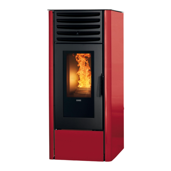
- Page 1 STUFA A PELLET DEA ECO 12 INSTALLAZIONE, USO E MANUNTENZIONE, CONSIGLI UTILI Main Revision 1.3 FPH_supplement: 001 ITALIANO FRANÇAIS ENGLISH ESPAÑOL Cod. CS.IST.SE12 Rev. 1.3 S.R.L.
-
Page 2: Table Of Contents
GENERAL INDEX INTRODUCTION ................................ 3 ............................ 3 MPORTANT SECURITY INSTRUCTIONS ................................ 3 FEW PRECAUTIONS .................................. 3 NTENDED USE .............................. 4 NSTALLATION EGULATIONS ................................ 4 EALTH AND AFETY THE MACHINE AND THE PELLETS .......................... 5 ................................ 5 TOVE COMPONENTS .............................. 6 ONNECTIONS DATA SHEET ................................ 7 ECHNICAL FEATURES ................................ 8 ELLET FEATURES ... - Page 3 Technical Assistance Centre (TAC) for the initial start-up and calibration of your stove. In thanking you once again for trusting KLOVER products, we also wish to inform you that these models are the result our forty years experience in the construction of solid-fuel products for domestic heating.
-
Page 4: Introduction
NEVER open the door of the stove during normal operation. Intended use The automatic operation DEA ECO stove by Klover is designed for heating your entire home. The stove works exclusively with wood pellets and only with the hearth door shut. Never open the door while the device is operating. - Page 5 Approved Document J. Health and Safety Care must be taken when installing a Klover pellet stove to ensure that the requirements of the Health and Safety at Work Act are met. Handling Adequate facilities must be available for loading, unloading and site handling the appliance bearing in mind the weight of the appliance.
-
Page 6: The Machine And The Pellets
THE MACHINE AND THE PELLETS Stove components The stove is delivered with the following equipment: ONE USE, INSTALLATION AND MAINTENANCE GUIDE; ONE WARRANTY COUPON; ONE POWER SUPPLY CABLE. This manual is an integral part of the machine: if the stove is sold, it must be handed down to the new owner. AMBIENT TEMPERATURE FLUE GAS... -
Page 7: Onnections Data Sheet
Connections data sheet REAR VIEW S = Ø 80 mm M FLUE GAS OUTLET A = Ø 33 mm AIR EXTRACTION DEVICE E = SWITCH WITH ELECTRIC CABLE CONNECTION... -
Page 8: Echnical Features
Technical features Nominal heat input 13,6 (2,5) Nominal heat output (reduced) 12,1 (2,3) (Reduced) nominal output performance 89,1 (93,2) CO at 13% oxygen at (reduced) nominal output 0,019 (0,059) Combustion gas mass at nominal heat output (reduced) 8,2 (4,4) Average flue gas temperature at nominal heat output (reduced) °... -
Page 9: Ellet Features
Pellet features The stove has been tested with all types of pellets available on the market. The pellets used must also have the following features: Diameter 6 mm; Maximum length 35 mm; Maximum humidity content 8 – 9 %; ... -
Page 10: Requirements Of The Place Of Installation
REQUIREMENTS OF THE PLACE OF INSTALLATION Positioning The initial phase for best stove installation is to determine its optimal location; the following elements need to be considered: The possibility of including an external air vent; The possibility of creating a straight flue, preferably coaxial to the stove outlet; ... - Page 11 Fig. A Chimney and Flue pipe The chimney is essential to the efficient operation of a Klover appliance. The chimney should be designed and constructed according to these instructions, and relevant regulations including Building Regulations Approved Document J.
- Page 12 Existing chimneys: Existing masonry chimneys should be lined with flexible stainless steel liner and the liner should be insulated. All connections must be appropriately sealed. Existing chimneys must be inspected, be clear of obstruction and have been swept clean immediately before installation of the lining system.
- Page 13 Height and draught: In order for the appliance to perform satisfactorily the chimney height must be sufficient to ensure a draught of 12 Pa so as to clear the products of combustion and prevent smoke problems into the room. A chimney height of not less than 4.5 m measured vertically from the outlet of the stove to the top of the chimney should be satisfactory.
-
Page 14: Electrical Connection
During the final wiring of the circuit, only use components with a suitable electrical protection rating. KLOVER srl declines all responsibility for injury to persons and animals or damage to objects due to failure to connect the stove to earth or to comply with IEC specifications. -
Page 15: Cleaning And Maintenance
CLEANING AND MAINTENANCE Precautions before cleaning Before carrying out any cleaning or maintenance operations, make sure that: The stove is turned off and all its parts have cooled down completely; The ash is completely cold; Before re-starting the stove, re-install all previously removed components. During cleaning operations, use the personal protection devices specified in Directive 89/391/EEC. -
Page 16: Xtraordinary Cleaning
Empty the ash drawer. ATTENTION: use suitable “bin” type vacuum cleaners equipped with a fine mesh filter, in order to prevent part of the ash from being spilled and thus damaging the cleaner itself. Extraordinary cleaning To be performed at least every 30 days. Perform routine cleaning;... - Page 17 Dismount the 4 flue diverters (2 on the right and 2 on the left) placed on the combustion chamber sides and scrape the internal walls with a spatula removing any deposit. Fare attenzione a non forzare con il tubo del aspiracenere le alette dell’aspiratore fumi.
-
Page 18: Leaning The Ceramic Glass
For correct functioning, it is necessary to use a suction device to remove the sawdust deposit on the base of the tank at least every 15 days. The pellet tank must be emptied at the end of every season. Cleaning the ceramic glass Always clean the glass when the stove is off and completely cold. -
Page 19: The Display
THE DISPLAY The device's operating mode is displayed on the console. After turning on the menu, it is possible to choose many types of visualisations and perform the available settings according to the selected menu. The picture below describes the meaning of the buttons and LEDs present on the console. Programmable thermostat LED Mode - power - parameter display... - Page 20 Button functions BUTTON MODE ACTION TEMPERATURE SET... Decreases the TEMPERATURE SET temperature value POWER SET... Decreases the POWER SET value MENU... Moves to the previous menu MENU PROGRAMMING... Decreases the value of the selected menu PARAMETERS PROGRAMMING... Decreases the value of the parameter TEMPERATURE SET...
-
Page 21: The Menu
THE MENU Keeping button 1 pressed for about two seconds allows for accessing the Menu. The latter is divided into different entries and levels accessing the PCB programming and setting options. Buttons 1 and 2 allow for scrolling the menus to be modified. Button 3 allows for selecting the menu to be accessed and/or modified. - Page 22 M2-4 Weekend prog. Weekend timer Allows for enabling the weekend programme Start 1st weekend Switch-on time first weekend programme Stop 1st weekend Switch-off time first weekend programme Start 2nd weekend Switch-on time second weekend programme Stop 2nd weekend Switch-off time second weekend programme M2-5 Exit Exit the programmable thermostat M3 –...
- Page 23 Moreover, by setting OFF in the time field, the clock ignores the corresponding command. WEEKLY PROGRAMME 1 MENU LEVEL SELECTION MEANING POSSIBLE VALUES M2-3 Weekly prog. Start Prog.1 Switch-on time first weekly programme Time - OFF Stop Prog.1 Switch-off time first weekly programme Time - OFF Mon.
- Page 24 TIP: in order to avoid confusion and any undesired switching on/off operations, only activate a single programme at a time if you do not know exactly what you desire obtaining. Deactivate the daily programme if you wish to use the weekly programme instead. Always keep the weekend programme deactivated when using the weekly programmes 1, 2, 3 and 4.
-
Page 25: Initial Startup
INITIAL START-UP Pellet loading and connection to the electricity network Perform the following operations: Connect the stove to the electrical system using the cable supplied; Position the switch on the rear side of the stove on “( ”׀on); ... -
Page 26: Tove Work Phase
Stove work phase During the work phase, by pressing button 1 first then buttons 1 or 2, it is possible to set a "SET TEMPERATURE" value (general temperature of the room where the stove is installed); when this temperature is reached, the stove enters the economy mode in which fuel consumption is reduced to a minimum. -
Page 27: Odifying The Working Power Setting
Modifying the working power setting To modify the ambient temperature, simply select the “SET POWER” mode by pressing button 2. Press buttons 1 and 2 for increasing or decreasing - respectively - the desired power. During this operation, the display will appear as in the picture below. Pot2 After setting the desired value, press button 3 or wait a few seconds. -
Page 28: What Happens If
WHAT HAPPENS IF.. …the pellets do not ignite In case of ignition failure. The “IGNITION FAILURE“ alarm message appears. Cancel the alarm by pressing button 3 for a few seconds then restore the stove to the standard conditions..the fire door is improperly opened or closed In case the door is open or closed improperly, the gearmotor cannot be powered electrically, therefore the stove does not switch on. -
Page 29: Pcb Parameters
AT THE FACTORY. THESE PARAMETERS STEM FROM ACCURATE TESTS WITH VARIOUS TYPES OF PELLETS AND MUST NOT BE MODIFIED WITHOUT PRIOR AUTHORISATION FROM KLOVER srl, IN ORER TO AVOID JEOPARDISING THE STOVE'S OPERATION. THE COMPANY SHALL NOT BE HELD LIABLE FOR ANY DAMAGES CAUSED BY INCORRECT PARAMETER ENTRY. - Page 30 “Various calibrations” (Menu M8 – 2) (Firmware H02_250117) Parameter Description Display writing Measurement Value field Database o1 Pr38 Re-ignition block RE-IGNITION BLOCK Minutes 0 – 10 EXTRACTOR OFF Pr39 Flue gas extractor switch-off time Minutes 0 – 20 MINUTES Pr40 Pre-loading time in ignition IGNITION PRE-LOADING Seconds...
-
Page 31: Wiring Diagram
WIRING DIAGRAM PHASE BLACK NEUTRAL WHITE EARTH GROUND... - Page 32 The document must be shown to the Technical Assistance Centre, if required. A copy of the warranty coupon sent to KLOVER s.r.l. must be stored together with the purchase document received.
- Page 33 ...
Need help?
Do you have a question about the DEA ECO 12 and is the answer not in the manual?
Questions and answers