Sign In
Upload
Download
Table of Contents
Contents
Add to my manuals
Delete from my manuals
Share
URL of this page:
HTML Link:
Bookmark this page
Add
Manual will be automatically added to "My Manuals"
Print this page
×
Bookmark added
×
Added to my manuals
Manuals
Brands
Innotech Manuals
Controller
MAXIM 1010
Installation instructions manual
Innotech MAXIM 1010 Installation Instructions Manual
Maxim series
Hide thumbs
1
2
3
4
Table Of Contents
5
6
7
8
9
10
11
12
13
14
15
16
17
18
19
20
21
22
23
24
25
26
27
28
29
30
31
32
33
34
35
36
37
38
39
40
41
42
43
44
45
46
47
48
49
50
51
52
53
54
55
56
57
58
59
60
page
of
60
Go
/
60
Contents
Table of Contents
Bookmarks
Table of Contents
Table of Contents
Chapter 1 - Preliminary Information
Scope
1-1.1 Systems Covered by this Manual
1-1.2 Terminology Used in this Manual
1-1.3 Document Layout
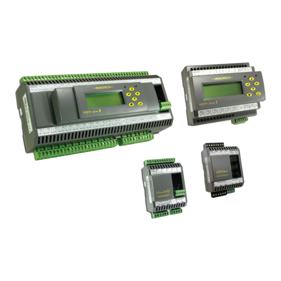
Overview of MAXIM Series Controllers
1-2.1 Primary Network Controllers
Table 1-2: Features of MAXIM Series Controllers
1-2.2 Sub System Network Controllers
1-2.3 Sub System Gateway (IG01)
Special Considerations
Tools and Materials
1-2.4 MAXIM I Controller
Chapter 2 - Mechanical Installation
Overview
Figure 2-1: Typical Enclosure Installation
Physical Description and Dimension Diagrams
2-2.1 Overview
2-2.2 MAXIM I, II, III, and 1010 Controllers
Figure 2-2: MAXIM I and MAXIM II Controller Dimensions
2-2.3 Minimax, Micromax, Vavmax, and IG01
Figure 2-3: MAXIM III and MAXIM 1010 Controller Dimensions
Figure 2-4: Minimax, Micromax, Vavmax and IG01 Controller Dimensions
General Installation Information
2-3.1 Overview
2-3.2 General Installation Guidelines
Figure 2-5: LCD Optimum Viewing Angle
2-3.3 Installing on DIN Rail
Figure 2-6: DIN Rail Dimensions
Figure 2-7: Installing MAXIM Controller on a DIN Rail
Chapter 3 - Electrical Installation
Overview
Electrical Installation Practices
MAXIM Controller Wiring
Figure 3-1: MAXIM Series III Connection Details Generated with Maxcon Software
3-3.1 MAXIM I, II, III, and 1010 Controllers
Figure 3-2: MAXIM I Controller Terminal Connection Layout
Figure 3-3: MAXIM II Controller Terminal Connection Layout
Figure 3-4: MAXIM III Controller Terminal Connection Layout
Figure 3-5: MAXIM 1010 Controller Terminal Connection Layout
Figure 3-6: Analogue Output Driving Multiple Solid State Relays
Table 3-4: MAXIM 1010 Universal Outputs
3-3.2 Minimax Controllers (MM01 / MM02)
Figure 3-7: Minimax (MM01 & MM02) Controller Terminal Connection Layout
Table 3-5: Minimax Power Source Specifications
3-3.3 Vavmax and Micromax Controllers
Figure 3-8: Vavmax and Micromax Controller Terminal Connection Layout
Table 3-10: Vavmax and Micromax Power Terminals
Table 3-9: Vavmax and Micromax Power Source Specifications
3-3.4 IG01 Sub System Gateway
Figure 3-9: IG01 Sub System Gateway Terminal Connection Layout
Table 3-14: IG01 Sub System Gateway Power Terminals
Chapter 4 - Network Installation
Overview
Figure 4-1: Innotech Network Diagram
Chapter 5 - Commissioning
Overview
Inspect the Installation
Figure 5-1: Checking Power Input Voltage
Figure 5-2: Checking Universal Inputs for 0V
Figure 5-3: Checking Digital Relay Output Wiring
Figure 5-4: Checking Analogue Output Voltage
Figure 5-5: Checking Analogue Output Resistance
Figure 5-6: End of Cable Jumper Locations on Sub Network Devices
Appendix A - Using the CT01 Commissioning Tool
Overview
Connecting to Subsystem Network Devices
A-2.1 Connecting Directly to Controller on Sub System Network
Figure A-1: Connecting the CT01 to a Sub System Network Device
A-2.2 Connecting to Sub System Gateway (IG01)
Figure A-2: Connecting the CT01 to a Sub System Gateway IG01
A-2.3 Connecting to Sub System Network
Figure A-3: Connecting the CT01 to a Sub Network Device
A-2.4 CT01 Menus and Navigation
Logging Onto the Controller
Figure A-4: CT01 Interface - Navigation and Menus
Vavmax Settings
Commissioning
A-5.2 Configuring the K-Factor
A-5.1 Calibration of Sensors
Customer Assistance
Innotech Support
Advertisement
Quick Links
1
1-1.1 Systems Covered by this Manual
2
Logging Onto the Controller
3
A-2.4 Ct01 Menus and Navigation
Download this manual
MAXIM Series Controllers
INSTALLATION INSTRUCTIONS
Table of
Contents
Previous
Page
Next
Page
1
2
3
4
5
Advertisement
Table of Contents
Need help?
Do you have a question about the MAXIM 1010 and is the answer not in the manual?
Ask a question
Questions and answers
Related Manuals for Innotech MAXIM 1010
Controller Innotech MAXIM I Installation Instructions Manual
Maxim series (60 pages)
Controller Innotech M2K03 User Instructions
(3 pages)
Controller Innotech M2K04 User Instructions
(3 pages)
Controller Innotech M2K01 User Instructions
(2 pages)
Controller Innotech Micro2000 M2K05 Manual
(6 pages)
Controller Innotech Micro2000 M2K04 Manual
Micro2000 controller (6 pages)
Controller Innotech Micro2000 M2K06 Manual
Micro2000 controller (6 pages)
Controller Innotech Micro2000 M2K07 Manual
(6 pages)
Controller Innotech MS1-05 Manual
Microcontroller (7 pages)
Controller Innotech Micro2000 M2K02 Manual
(6 pages)
Controller Innotech Micro2000 M2K08 Manual
(6 pages)
Controller Innotech Omni Series Installation Instructions Manual
(90 pages)
Controller Innotech GENII CSFCAH REM Manual
Control station with 3 speed fan (4 pages)
Table of Contents
Print
Rename the bookmark
Delete bookmark?
Delete from my manuals?
Login
Sign In
OR
Sign in with Facebook
Sign in with Google
Upload manual
Upload from disk
Upload from URL


Need help?
Do you have a question about the MAXIM 1010 and is the answer not in the manual?
Questions and answers