Advertisement
Quick Links
Models:
M2K08
3 Speed FAN, 1 COOL, 1 HEAT Controller, 7 day - 4 Event
Time Clock or Timer, with Condenser Water Pump Interlock
The Clock is not battery backed. Time and Date will need to
be set every time power is cycled if the Time Clock function is
enabled. Schedules and Parameters are saved even if power
is lost.
Specifications
Power Supply
• Voltage:
240VAC ±10% @ 50/60Hz
• Power Consumption:
7VA max
Inputs
• 10kΩ Thermistor temperature sensor
• Digital Input for Switched contact
Outputs
Relay # 1, 2,
Voltage free relay contacts:
3, 4:
Normally Open
Relay # 5
Voltage free relay contacts:
Normally Open
Connection Between Controller and Control Station
• 4 way connection via 4 core plus screen cable
Control Station Terminal Identification
• IN 1
Temperature Sensor Input
• IN 2
Digital Input for Switched Contact
• IN 3
Verify Signal Feedback Input
• GND
Common for Inputs and Cable Shield
• +12V
Power from Controller
• Comms
Comms to Controller
• GND
Ground from Controller
Controller Terminal Identification
240 Volt Power connection to Control Unit:
•
Earth
• N
Neutral Supply
• 240V~
Mains 240VAC Supply
Output Relays
• NO
Normally Open Contact
• COM
Common Contact
Comms Terminals
• +12V
Power to Control Station
• Comms
Comms from Control Station
• GND
Ground to Control Station
Temperature Ratings
• Storage:
0 to 50°C non-condensing
• Operating:
0 to 40°C non-condensing
• Sensor Input:
5 to 35°C
10A resistive
6A inductive
2A resistive
0.5A inductive
© MASS ELECTRONICS Pty Ltd 2007
M2K08
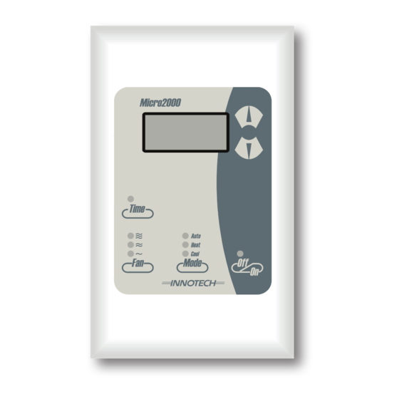
Micro2000 Controller
Application
The Innotech M2K08 Controller is designed to provide complete control
of air conditioning systems for commercial applications. Specifically for
applications where a Condenser Pump Interlock System is required.
Features
• Condenser Water Pump Interlock Control
• LED Display of Temperature and Program functions
• Control Station fits standard electrical wall plates
• Four core screened cable simplifies connection between the Control
Station and Controller
• Adjustable Proportional Band, Dead Zone, Compressor Restart Time
and Setpoint Range
• Able to operate as 1 cool, 1 electric heating or as reverse cycle heating
or cooling
• Three Speed Fan Control
• 7 Day 24hr Real Time Clock or Adjustable Timer function
• Programmable Schedules, 4 events per day
• All adjustments from the Control Station
DS 9.08
August 2013
Advertisement

Subscribe to Our Youtube Channel
Related Manuals for Innotech Micro2000 M2K08


Summary of Contents for Innotech Micro2000 M2K08
- Page 1 • N Neutral Supply • 240V~ Mains 240VAC Supply Application Output Relays The Innotech M2K08 Controller is designed to provide complete control • NO Normally Open Contact of air conditioning systems for commercial applications. Specifically for • COM Common Contact applications where a Condenser Pump Interlock System is required.
-
Page 2: Installation
Maximum terminal cable entry is 1.5mm² wire. Relay #1 Fan Low (10A Relay. Common and Normally Open Contact) 2. Wire in accordance with INNOTECH connection diagrams and Relay #2 Fan Mid (10A Relay. Common and Normally Open Contact) local bylaws or refer to your local distributor. -
Page 3: Programming Your Controller
Page 3 DS 9.08 - M2K08 - Micro2000 Controller August 2013 Time Clock Mode button to go back to programming mode selection. When Parameter 10 is set to "On", the Time button allows 4. If "SCH" was selected in step 2, you can now set / edit the you to enable or disable the Time Clock. - Page 4 Page 4 DS 9.08 - M2K08 - Micro2000 Controller August 2013 Parameters Parameter 8: HEA / COOL Parameter 0: Sensor Calibration The Display will show either HEA or COOL to select if the reversing The display will show the Sensor Temperature. To offset the sensor valve is energised for cooling or energised for heating.
- Page 5 4. The Micro2000 outputs may remain On or Off due to burning or deposition of the output relays. External safety measures must be provided for such problems to ensure safety in the system. 5. Follow Innotech wiring diagrams and the installation / wiring instructions contained in this Datasheet. © MASS ELECTRONICS Pty Ltd 2007...
-
Page 6: Your Distributor
Phone: +61 7 3421 9100 Fax: +61 7 3421 9101 Email: sales@innotech.com.au www.innotech.com.au © MASS ELECTRONICS Pty Ltd 2007 The INNOTECH device and the word INNOTECH are registered or unregistered trademarks of Mass Electronics Pty Ltd in Australia, USA and other countries...
Need help?
Do you have a question about the Micro2000 M2K08 and is the answer not in the manual?
Questions and answers