Table of Contents
Advertisement
Quick Links
Advertisement
Table of Contents

Related Manuals for Innotech Omni Series


Summary of Contents for Innotech Omni Series
- Page 1 Omni INSTALLATION INSTRUCTIONS...
-
Page 2: Proprietary
Mass Electronics Pty Ltd. Trademark The term ‘Innotech’ used in this manual is a trademark of Mass Electronics Pty Ltd trading as Innotech Control Systems Australia. 'Microsoft' and 'Windows' are registered trademarks of Microsoft Corporation in the United States and other countries. -
Page 3: Document Management
Document Management Document Title: Omni Installation Instructions Revision History Version Date Summary of Changes Number September 2017 Document first edition March 2018 Update Omni U10 REM Images Specification update for supported U10 REMs on Omni C20 August 2018 controllers Edition 1.2 dated 08.08.2018 Page 3 ©... - Page 4 This page has been left intentionally blank. Edition 1.2 dated 08.08.2018 Page 4 © Mass Electronics Pty Ltd 2017...
-
Page 5: Table Of Contents
Contents Proprietary ........................2 Trademark ......................... 2 Disclaimer ......................... 2 Document Management ....................3 Preliminary Information 1-1 Introduction ......................12 1-1.1 Systems Covered by this Manual ................12 1-1.2 Scope of this Technical Manual................13 1-2 Specifications Table ....................14 1-3 Special Considerations .................... 15 1-4 Installation Plans ..................... - Page 6 4-4.1 Setting the IP and BACnet Instance via USB Connection ........60 4-4.2 Ethernet ........................62 4-4.3 RS-485 Wiring Topology ..................67 4-4.4 Ethernet and RS-485 ....................70 4-4.5 Connection of Innotech Legacy Devices ..............70 Edition 1.2 dated 03.08.2018 Page 6 © Mass Electronics Pty Ltd 2017...
- Page 7 5-1.5 Check EOL Jumpers ....................81 5-1.6 Install Software and Configure the Controller(s) ...........82 5-1.7 Initial Tests ......................86 5-1.8 Final System Check ....................88 Customer Assistance ...................... 89 Innotech Support ......................89 List of Illustrations Figure 2-1: Omni C40D Dimensions and Identification ............19 Figure 2-2: ...
- Page 8 Figure 4-6: Example Controller Wiring Topology - Ethernet with switch ........63 Figure 4-7: Ethernet - TCP/IP Settings ..................64 Figure 4-8: Ethernet - Innotech TCP Settings ................64 Figure 4-9: Protocols Settings - BACnet ...................65 Edition 1.2 dated 03.08.2018 Page 8 © Mass Electronics Pty Ltd 2017...
- Page 9 Ethernet - BACnet IP Public Settings ..............66 Figure 4-12: Example U10 Wiring Topology - RS-485 ..............67 Figure 4-13: RS-485 - Innotech Net Settings ................68 Figure 4-14: RS-485 - Innotech Global Settings ................68 Figure 4-15: RS-485 - BACnet MS/TP Settings ................69 Figure 4-16: ...
- Page 10 List of Tables Table 1-1: Manual Scope ......................13 Table 1-2: Specifications Table ....................14 Table 3-1: Nominal Resistance for Wire Sizes at 20°C .............33 Table 3-2: Programmable Point Specifications ..............34 Table 3-3: Recommended Wiring - C40 ...................38 Table 3-4: Recommended Wiring - C20 ...................41 Table 3-5: ...
-
Page 11: Preliminary Information
Omni INSTALLATION INSTRUCTIONS Preliminary Information... -
Page 12: Introduction
Although the intent of this manual is to simplify the installation task, instructions contained in this manual are based on the assumption that installation of an Innotech Omni Control System will be accomplished by technically qualified personnel. Also, these instructions assume that installation personnel are familiar with local regulations, codes and safety requirements. -
Page 13: 1-1.2 Scope Of This Technical Manual
Omni Installation Instructions 1-1.2 Scope of this Technical Manual This technical manual contains: Manual Scope Table 1-1: Chapter Description Chapter 1 - Contains installation related information of a general nature such as general safety considerations and pre-installation requirements. Preliminary Information Contains instructions and related data to facilitate the mechanical Chapter 2 - installation of components of the Omni System. -
Page 14: Specifications Table
4.5W 4.5W • The real-time clock battery is user replaceable but should only be replaced by qualified Innotech service technicians or distributors. The battery is located in the expansion bay on all controller models. • The controller's MicroSD card also contains PDF documents. For the latest documents, visit www.innotech.com.au. -
Page 15: Special Considerations
• Local safety regulations, building codes and ordinances must be complied with during installation. In cases of conflict with procedures in this manual, contact Innotech or its authorised representative for clarification. • To prevent damage to equipment, avoid applying electrical power to the equipment prior to checking the system, unless specifically instructed to do so in this manual. - Page 16 Omni Installation Instructions This page has been left intentionally blank. Edition 1.2 dated 16.08.2018 Page 16 © Mass Electronics Pty Ltd 2017...
-
Page 17: Mechanical Installation
Omni INSTALLATION INSTRUCTIONS Mechanical Installation... -
Page 18: Introduction
It is highly recommended that the Omni Series Controllers and peripheral devices be installed and mounted in a steel enclosure to minimise the effect of Electro Magnetic Interference (EMI). -
Page 19: 2-2.1 Omni C40 Controller Dimensions & Identification
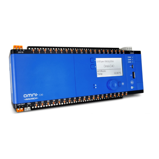
Omni Installation Instructions 2-2.1 Omni C40 Controller Dimensions & Identification The Omni C40 & C40D Controllers are the largest controllers in the Omni controller range. The controller features 40 programmable points, 3 RS-485 comms inputs, 2 RJ45 ethernet ports, USB A and Mini-B connections and an ISS RS-485 input. -
Page 20: Figure 2-3: Omni Omh01 Hmi
Omni Installation Instructions Watches Alarms LCD Screen Warning / Alarm LEDs Navigation Wheel Back Button Figure 2-3: Omni OMH01 HMI EOL Jumper RS485 Port 3 (Set) EOL Jumper RS485 Port 2 (Not Set) EOL Jumper RS485 Port 1 (Not Set) Backup Battery Expansion Slot Figure 2-4: ... -
Page 21: 2-2.2 Omni C20 Controller Dimensions & Identification
Omni Installation Instructions 2-2.2 Omni C20 Controller Dimensions & Identification The Omni C20 & C20D Controllers feature 20 programmable points, 3 RS-485 comms inputs, 2 RJ45 ethernet ports, USB A and Mini-B connections and an ISS RS-485 input. Optional HMI shown in C20D image. Programmable Comms Comms... -
Page 22: Figure 2-8: Omni Omh01 Hmi
Omni Installation Instructions Watches Alarms LCD Screen Warning / Alarm LEDs Navigation Wheel Back Button Figure 2-8: Omni OMH01 HMI EOL Jumper RS485 Port 3 (Set) EOL Jumper RS485 Port 2 (Not Set) EOL Jumper RS485 Port 1 (Not Set) Backup Battery Expansion Slot Figure 2-9: ... -
Page 23: 2-2.3 Omni C14 Controller Dimensions & Identification
Omni Installation Instructions 2-2.3 Omni C14 Controller Dimensions & Identification The Omni C14 & C14D Controllers feature 14 programmable points, 2 RS-485 comms inputs, 1 RJ45 ethernet port and a USB Mini-B connection. Optional HMI shown in C14D image. Comms Programmable Comms Indicators... -
Page 24: Figure 2-13: Omni Omh01 Hmi
Omni Installation Instructions Watches Alarms LCD Screen Warning / Alarm LEDs Navigation Wheel Back Button Figure 2-13: Omni OMH01 HMI EOL Jumper RS485 Port 2 (Set) Not Used EOL Jumper RS485 Port 1 (Not Set) Backup Battery Expansion Slot Figure 2-14: Expansion Bay EOL Jumpers Figure 2-15: ... -
Page 25: 2-2.4 Omni U10 Remote Expansion Module Dimensions & Identification
Omni Installation Instructions 2-2.4 Omni U10 Remote Expansion Module Dimensions & Identification The Omni U10 can be used on the Omni C40 & C20 controllers. Each U10 adds an additional 10 Programmable Points to the connected Omni controller. The flexibility and features such as self- diagnostics, individual LED status indication and the ability to program each point as an Input or Output are all available as on the host controller. -
Page 26: Expansion Bay
Expansion Cards cannot be installed in the Omni C14, although it does still have an expansion bay. Expansion cards are to be installed / replaced by qualified Innotech service technicians. 2-3.1 Expansion Cards Omni controller models C40 and C20 provide for the installation of optional modules for High Level Interface communication cards. -
Page 27: 2-3.2 Backup Battery Replacement
Contains a Lithium Type Battery, Dispose of Properly. (In accordance with local regulations) Caution: Risk of explosion if battery is replace by an incorrect type. The real-time clock battery is user replaceable but it is recommended that it be replaced by qualified Innotech service technicians. -
Page 28: Installation Instructions
Omni Installation Instructions 2-4 Installation Instructions A steel enclosure is recommended to contain the system with the aim of minimising EMI from surrounding equipment. To allow for the number of cables to enter and leave the enclosure, the minimum dimensions of slotted cable ducts should be 45mm x 45mm with 65mm clearance from the cable ducts to the terminals of the units. -
Page 29: Figure 2-21: Din Rail Installation
Omni Installation Instructions 2-4.2.1 Installation 1. Pull the DIN rail release tab down. 2. Align the DIN rail clip on the top edge of the DIN rail. 3. Lower the controller so it is level and push the DIN rail clip upwards to secure the device. 2-4.2.2 Removal • Pull the DIN rail release tab down until it releases from the bottom edge of the DIN rail, and then pull the bottom away and lift up. -
Page 30: Hmi Installation
2-5 HMI Installation 2-5.1 OMH01 Retrofit Onboard HMI The OMH01 retrofit HMI display can only be installed by Innotech technical personnel. Refer to the OMH01 Installation Instructions supplied with the HMI for the correct installation procedure. 2-5.2 OMH02 External USB HMI Display Module The external HMI can be mounted in the cabinet near the Omni controller(s) or used handheld. -
Page 31: Electrical Installation
Omni INSTALLATION INSTRUCTIONS Electrical Installation... -
Page 32: Introduction
Instead, this manual provides examples of installations that are considered typical. Innotech recognises that the installation examples described in this manual may not meet the user’s requirements. However, information in this document should be used as a guide for all installations, regardless of whether the specific circumstances match the examples given. -
Page 33: Table 3-1: Nominal Resistance For Wire Sizes At 20°C
Omni Installation Instructions Cabling plays an important role in the installation of Omni system. The following general cabling guidelines should be observed: In all cases, use electromagnetic-shielded cable for sensor wiring: • When necessary to protect cabling from physical damage, both shielding and physical protection may be provided by running the cable in a metal conduit. -
Page 34: Programmable Point (Ui/O) Specifications
Omni Installation Instructions 3-3 Programmable Point (UI/O) Specifications Omni devices are equipped with Programmable Points (UI/Os), which can be configured with Focus software to be used as inputs or outputs. Each Universal Input/Output has a signal terminal (+) and a reference terminal (–). The types of inputs and outputs that can be configured and the respective range for each per the table below. - Page 35 For High Side and Toggle Switching modes, maximum available power is limited (45mA). For Low Side Switching, each channel can switch 200mA. Caution must be used when using Low Side Switching. For more information, contact your Innotech representative. Voltage Output Range...
-
Page 36: Digital Controller Wiring
Figure 3-1: Focus Generated Wiring Diagram Example 3-4.1 Common Programmable Point Information Omni controllers are equipped with Programmable Points that can be configured using Innotech Focus software to suit a wide range of applications. Each Programmable Point has a signal terminal (+) and a reference terminal (–) and can be configured as Inputs or Outputs. -
Page 37: 3-4.2 Omni C40/D Controller
Omni Installation Instructions 3-4.2 Omni C40/D Controller Figure 3-2 shows the input/output connection groups for the Omni C40 Controller. The controller uses Phoenix type plug-in terminal strips located around the controller’s perimeter. • Power Input (3-4.2.1) • Programmable Points (UI/O) (3-4.2.2) • 24V Output (3-4.2.3) • ISS Input (3-4.2.4) -
Page 38: Figure 3-3: Omni C40/D 24V Input Terminals
Omni Installation Instructions 3-4.2.1 Power Input The Omni C40 Controller power requirements are either AC or DC as below: • 24VAC ±20%, 50/60 Hz • 24VDC (18-35VDC) • Power Consumption: 30 Watts max. (load dependent) The Omni C40 has polarity independent supply wiring. The 24V and 0V wiring can be used in either terminal 1 or 2 per the image below. - Page 39 Innotech's Innotech Smart Sensor (ISS) communication protocol. 3-4.2.5 RS-485 Comms The Omni C40 Comms Inputs are provided for communications via BACnet MS/TP and Innotech Protocols (Maxim / Genesis II) and for connecting to a computer (using a USB Converter), Omni Controllers, U10 Remote Expansion Module (REM) and other means of communication via the RS-485 terminals.
-
Page 40: 3-4.3 Omni C20/D Controller
Omni Installation Instructions 3-4.3 Omni C20/D Controller Figure 3-4 shows the input/output connection groups for the Omni C20 Controller. The controller uses Phoenix type plug-in terminal strips located around the controller’s perimeter. • Power Input (3-4.3.1) • Programmable Points (UI/O) (3-4.3.2) • 24V Output (3-4.3.3) • ISS Input (3-4.3.4) -
Page 41: Figure 3-5: Omni C20/D 24V Input Terminals
Omni Installation Instructions 3-4.3.1 Power Input The Omni C20 Controller power requirements are either AC or DC as below: • 24VAC ±20%, 50/60 Hz • 24VDC (18-35VDC) • Power Consumption: 30 Watts max. (load dependent) The Omni C20 has polarity independent supply wiring. The 24V and 0V wiring can be used in either terminal 1 or 2 per the image below. - Page 42 Innotech's Innotech Smart Sensor (ISS) communication protocol. 3-4.3.5 RS-485 Comms The Omni C20 Comms Inputs are provided for communications via BACnet MS/TP and Innotech Protocols (Maxim / Genesis II) and for connecting to a computer (using a USB Converter), Omni Controllers, U10 REMs and other means of communication via the RS-485 terminals.
-
Page 43: 3-4.4 Omni C14/D Controller
Omni Installation Instructions 3-4.4 Omni C14/D Controller Figure 3-6 shows the input/output connection groups for the Omni C14 Controller. The controller uses Phoenix type plug-in terminal strips located around the controller’s perimeter. • Power Input (3-4.4.1) • Programmable Points (UI/O) (3-4.4.2) • RS-485 Comms (3-4.4.3) • Ethernet Communications Port (3-4.4.4) -
Page 44: Figure 3-7: Omni C14/D 24V Input Terminals
Omni Installation Instructions 3-4.4.1 Power Input The Omni C14 Controller power requirements are either AC or DC as below: • 24VAC ±20%, 50/60 Hz • 24VDC (18-35VDC) • Power Consumption: 30 Watts max. (load dependent) The Omni C14 has polarity independent supply wiring. The 24V and 0V wiring can be used in either terminal 1 or 2 per the image below. - Page 45 3-4.4.3 RS-485 Comms The Omni C14 Comms Inputs are provided for communications via BACnet MS/TP and Innotech Protocols (Maxim / Genesis II) and for connecting to a computer (using a USB Converter), Omni controllers and other means of communication via the RS-485 terminals.
-
Page 46: 3-4.5 Omni U10 Remote Expansion Module
Omni Installation Instructions 3-4.5 Omni U10 Remote Expansion Module Figure 3-8 shows the input/output connection groups for the Omni U10 REM. The controller uses Phoenix type plug-in terminal strips located around the controller’s perimeter. • Power Input (3-4.5.1) • RS-485 Comms (3-4.5.2) • USB Port (3-4.5.3) Programmable... -
Page 47: Figure 3-9: Omni U10 24V Input Terminals
Omni Installation Instructions 3-4.5.1 Power Input The Omni U10 REM power requirements are either AC or DC as below: • 24VAC ±20%, 50/60 Hz • 24VDC (18-35VDC) • Power Consumption: 8 Watts max. (load dependent) The Omni U10 has polarity independent supply wiring. The 24V and 0V wiring can be used in either terminal 1 or 2 per the image below. -
Page 48: Figure 3-10: U10 Connection To Omni
Omni Installation Instructions 3-4.5.2 RS-485 Comms The Omni U10 Comms Inputs provide the capability to connect to the host Omni controller and other daisy-chained U10 REMs. Connecting U10 REMs Omni U10 REMs are connected to the Omni network via the RS-485 Comms port(s). Connection is achieved using daisy-chaining. -
Page 49: 3-4.6 General Wiring Diagrams For Omni Controllers
Omni Installation Instructions 3-4.5.3 USB The Omni U10 has one USB Input, USB-Mini B. The USB-B connection is used for connection to a computer. 3-4.6 General Wiring Diagrams for Omni Controllers This section contains general wiring diagrams and images for the Omni controller. 3-4.6.1 Omni Earthed Mounted on DIN Rail Please Note: 24VAC Supply from... -
Page 50: Figure 3-15: Typical 4-20Ma Input To Omni
Omni Installation Instructions 3-4.6.4 Typical 4-20mA Input to Omni Typical Thermistor Input (4-20mA) to Omni Omni 24VAC Field Device 4-20mA Typical Screened 4-20mA Cable Input Figure 3-15: Typical 4-20mA Input to Omni 3-4.6.5 Typical 4-20mA Output From Omni Omni 24VAC Typical 4-20mA Screened... -
Page 51: Figure 3-19: Typical Two Wire 4-20Ma Input To Omni
Omni Installation Instructions 3-4.6.8 Typical 4-20mA Two Wire Input to Omni Omni 24VAC Sensor 4-20mA Typical Screened Humidity 24VDC Cable Input Figure 3-19: Typical Two Wire 4-20mA Input to Omni The Omni 24VDC Suppy is an unregulated, isolated 24VDC output, ~1.5W, 65mA max, overload protected. 3-4.6.9 Typical Thermistor Input to Omni Omni 24VAC... -
Page 52: Figure 3-22: Ptc Sensor Wiring Examples
Omni Installation Instructions 3-4.6.11 PTC Sensor Wiring The Omni Controller currently only supports PTC Sensors in 2 Wire mode. If using 3 or 4 wire PTC sensors, they can be wired as below: • 3 wire PTC Sensor à UIO+: 2 common wires à... -
Page 53: Networking
Omni INSTALLATION INSTRUCTIONS Networking... -
Page 54: Overview
Legacy Innotech devices can also be connected to an Innotech network with Omni controllers. Device connection is made by using Ethernet cables or by the RS-485 comms ports. Third party non-Innotech devices may also be able to be connected using Omni's native BACnet protocol. Edition 1.2 dated 20.08.2018 Page 54 ©... -
Page 55: 4-2.1 Definitions
The Global Points network provides a means for control data to be shared between Maxim or Genesis II Controllers on an Innotech network. The speed of the communication is relative to programmed Net Comms speed, being either 38,400 or 4,800. -
Page 56: Installation
4-3.1 Network Specifications The network type and baud rate determine the maximum recommended cable specifications. For RS-485 cable runs longer than the recommended lengths an Innotech Repeater IR11 or IR12 should be used. Repeaters may also be required if the number of devices connected to a network segment exceeds the maximum allowable number of devices for the specific network. -
Page 57: 4-3.3 Ethernet Considerations
CAT6 STP (Shielded Twisted Pairs), where each pair is individually shielded, are suited for use with multiple RS-485 communications channels such as the Innotech Primary Comms network. Shielding is required because of increased pair to pair capacitance, which is the primary culprit for Global/Net channel cross talk. -
Page 58: 4-3.5 Innotech Subsystem Wiring Considerations
The two ports on an Innotech Repeater IR11 or IR12 module reside on different sections of the system and each section can have up to the maximum of 32 nodes. With a one repeater, a total of 64 nodes can be connected on the system. - Page 59 As there is one ‘S’ terminal on a typical network device both the Global and Net screens are to be connected to this tie terminal. 4-3.5.4 Innotech Net / Global Comms Connections When other controllers are added to the network they must be installed in a manner that does not interrupt the integrity of the network.
-
Page 60: Cable Connection
RS-485 connections. IMPORTANT The next section for connecting to your controller using USB requires the latest version of iComm from the Innotech website to be installed. During installation device drivers will be installed to make this connection possible. 4-4.1 Setting the IP and BACnet Instance via USB Connection 1. -
Page 61: Figure 4-3: Login Screen Accessed Using Usb
169.254.2.100. Assuming the controller does not previously have a configuration installed, login using the default credentials. Username: Innotech, Password: 1111. If the controller contains a configuration, login using user credentials contained in the configuration. -
Page 62: 4-4.2 Ethernet
Omni Installation Instructions 4-4.2 Ethernet Be sure to adhere to cable connection standards for Ethernet connections. Omni C40 and C20 controllers can be connected by 'daisy chaining' the devices by utilising both ethernet ports. When routing through these Omni controllers, the Port Assignment > Ethernet > Mode setting must be changed to Switch. -
Page 63: Figure 4-6: Example Controller Wiring Topology - Ethernet With Switch
The TCP/IP details can be changed in several ways. • Change the details on the HMI (Port Assignment > Ethernet > Port # > TCP/IP) • Create a configuration in Innotech Focus software and transfer a configuration to the controller using the default IP address • Connect to the on-board web server by entering the default address into a supported web browser... -
Page 64: Figure 4-7: Ethernet - Tcp/Ip Settings
Figure 4-7: Ethernet - TCP/IP Settings 4-4.2.2 Ethernet (Innotech TCP) Innotech TCP's only setting is to specify the port (20000 default for Omni communication). This is used to disable TCP if required and is on by default. Figure 4-8: Ethernet - Innotech TCP Settings Edition 1.2 dated 20.08.2018... -
Page 65: Figure 4-9: Protocols Settings - Bacnet
Omni Installation Instructions If the BACnet protocol is to be used, ensure that the BACnet Device Instance has been changed to a unique number for each Omni controller. Figure 4-9: Protocols Settings - BACnet 4-4.2.3 Ethernet (BACnet IP Local - Device) Specify the Network Number and UDP port or accept the defaults. -
Page 66: Figure 4-11: Ethernet - Bacnet Ip Public Settings
Omni Installation Instructions 4-4.2.4 Ethernet (BACnet IP Public) • Specify the Network Number and UDP port or accept the defaults • Specify the maximum number of Foreign Devices • Specify the Public IP Address • Enter Address information into the Distribution Table Figure 4-11: Ethernet - BACnet IP Public Settings 4-4.2.5 Ethernet (Modbus TCP) 1. -
Page 67: 4-4.3 Rs-485 Wiring Topology
4-4.3 RS-485 Wiring Topology IMPORTANT Innotech recommends connection of Omni controllers using Ethernet. If you proceed to connect Omni controllers using this cable type, you will not be able to access the on-board web server, schedules and other advanced functions. - Page 68 Omni Installation Instructions 4-4.3.2 RS-485 (Innotech Net) Specify the Baud Rate, Timeout, Retries, Device Status Timeout and Message Speed Limit. Figure 4-14: RS-485 - Innotech Net Settings 4-4.3.3 RS-485 (Innotech Global) Specify the Baud Rate, Survey Limit, Network Timeout and Regeneration Timeout.
- Page 69 Omni Installation Instructions 4-4.3.4 RS-485 (BACnet MS/TP) Specify the Node Address, Network Number, Maximum Masters and Maximum Info Frames. The Max Masters setting must be set to the number of the last device on the network. Figure 4-16: RS-485 - BACnet MS/TP Settings 4-4.3.5 RS-485 (Modbus RTU) 4.
- Page 70 Omni Installation Instructions 4-4.3.6 RS-485 (Omni REM) If you are using one or more Omni U10 REMs, select your RS-485 port and change the protocol to Omni REM. Figure 4-18: RS-485 - Omni REM Settings Edition 1.2 dated 20.08.2018 Page 70 ©...
-
Page 71: 4-4.4 Ethernet And Rs-485
Figure 4-19: Example Controller Wiring Topology - Ethernet with U10s (RS-485) 4-4.5 Connection of Innotech Legacy Devices Connection of Innotech's legacy devices (non-Omni) is done using the Omni controller's RS-485 comms. The IG01 in the example below uses two comms ports to allow for data sharing. - Page 72 In this example, the IG01 and VAVMax The IG01 is connected to two comms channels, require EOL jumpers to be set. Innotech Net Comms and Innotech Global Comms. Also the C40 and last Omni U10 REM. Using two ports allows for data sharing.
- Page 73 Omni Installation Instructions This page has been left intentionally blank. Chapter 4 – Networking Page 73 © Mass Electronics Pty Ltd 2017...
-
Page 74: Commissioning
Omni INSTALLATION INSTRUCTIONS Commissioning... -
Page 75: Introduction
Omni Installation Instructions 5-1 Introduction The commissioning phase begins upon completion of the mechanical and electrical installation of the system and is the phase in which the user makes the system ready for operation. The commissioning process consists of performing the following procedures, which are explained elsewhere in this section: 5-1.1 - Inspect the Installation 5-1.2 - Check Input and Output Wiring... -
Page 76: 5-1.2 Check Input And Output Wiring
Omni Installation Instructions 5-1.1.2 Electrical Inspection • Make sure all sources of electrical power, including power to ancillary items are off • Check all input and output connections against the computer-generated wiring diagram supplied for your installation • Ensure all connections are in accordance with the wiring diagram and that connections are solidly made • Ensure all enclosures are solidly earthed • Check all input and output cabling;... -
Page 77: Table 5-1: Omni System Power Inputs
Omni Installation Instructions 5-1.2 Check Input and Output Wiring The purpose of checking the input and output wiring is two-fold. Firstly, the wiring is checked to verify that it is connected properly, thus ensuring proper operation of the system. Secondly, the wiring is also checked to ensure the absence of any external voltages that could damage an Omni product. -
Page 78: Figure 5-1: Omni Power Terminals
Omni Installation Instructions Terminals 1 & 2 in the image below are not polarity conscious, meaning EITHER terminal can be 24V or 0V. For the purposes of clarity in this document, terminal 1 will be used for 24V and terminal 2 for 0V. Figure 5-1: ... -
Page 79: Figure 5-3: Checking Ac Power Input
Omni Installation Instructions DIGITAL 240VAC POWER 24VAC VOLT-OHM POINT TRANSFORMER METER LIVE NEUTRAL EARTH OMNI DEVICE Figure 5-3: Checking AC Power Input DIGITAL VOLT-OHM METER POSITIVE 24VDC SUPPLY NEGATIVE COMMON OMNI DEVICE EARTH Figure 5-4: Checking DC Power Input Chapter 5 – Commissioning Page 79 ©... - Page 80 Omni Installation Instructions 5-1.2.2 Checking Digital Input/Output Wiring Digital input wiring to controllers and remote expansion modules should be checked to ensure the following conditions: • The digital signal source voltage is within the correct range • The signal polarity is correct for digital input signals with DC sources • Wiring to the signal actuator (switch, relay contacts, contact points, etc.) is correct CAUTION Avoid risk of electrical shock, observe all local electrical safety requirements.
-
Page 81: 5-1.3 Check Ethernet Connections
Omni Installation Instructions INPUT SOURCES Figure 5-5: Checking Digital Input Wiring 5-1.3 Check Ethernet Connections • Checks should be made to ensure that all the RJ45 connectors are fully seated and 'clicked' into the ethernet port on the Omni devices. • If external hubs or switches are used, ensure that the RJ45 connectors are fully seated and 'clicked' into the ethernet ports. -
Page 82: 5-1.5 Check Eol Jumpers
EOL jumpers to be set. Innotech Subnet Comms Comms Note: The IG01 is connected to two comms channels, Innotech Net Comms and Innotech Global Comms. Using two ports allows for data sharing. Figure 5-7: IG01 and Sub-Network EOL Placement Edition 1.2 dated 20.08.2018 Page 82 ©... -
Page 83: 5-1.6 Install Software And Configure The Controller(S)
• Installing Focus for the first time requires that your Innotech User Information be entered to retrieve your available licences. The licence is provided by Innotech to permit access to the Focus software. If a licence has not been provided, contact Innotech Control Systems using the contact details shown on the last page of this manual. -
Page 84: Figure 5-9: Start Menu And Omni Rem Addresser
Set the Port Assignment protocol to Omni REM. Set REM Address 5. Open the Omni REM Addresser software from the Innotech folder. Figure 5-9: Start Menu and Omni REM Addresser Edition 1.2 dated 20.08.2018 Page 84 © Mass Electronics Pty Ltd 2017... -
Page 85: Figure 5-10: Omni Rem Addresser - Rem Detected
Omni Installation Instructions 6. Connect a USB cable between your computer and the Mini-USB on the front of the Omni U10 REM. Note: The U10 REM does not need to be powered for addressing. 7. The U10 REM should be automatically detected. If not, specify the Comms Port to connect 8. -
Page 86: Figure 5-12: Omni Rem Upgrade Required
Omni Installation Instructions Upgrading a U10 REM An upgrade is available for the Omni U10 REM when a spanner icon is shown next to the REM. 1. Click the Upgrade button to upgrade the REM. You can force an upgrade at any time even when the spanner is not shown. -
Page 87: 5-1.7 Initial Tests
Omni Installation Instructions 5-1.7 Initial Tests Initial tests of the system involve the use of the Focus software to perform a thorough check of the system. The basic approach to performing these tests is to use the software to apply simulated inputs to the controller and to check the effect on the output circuits. - Page 88 Omni Installation Instructions 5-1.7.3 First Phase Testing Perform the first phase of initial tests of the system as follows: 1. Turn off all electrical power to the Omni System. 2. Connect the controller to the computer by finding it on a connected network. 3.
-
Page 89: 5-1.8 Final System Check
Omni Installation Instructions 5-1.8 Final System Check Final check of the system involves checking the operation of the system, performing any necessary adjustments and verifying that the system functions properly under normal operating conditions. The following are the procedures for performing final system checkout: 1. -
Page 90: Innotech Support
Innotech Support Innotech provides technical information on the Web to assist you with using its products. At www.innotech.com, you can find technical manuals, user instructions, and data sheets for all our products. For direct product support or product information, contact your local distributor, or an Innotech representative.
Need help?
Do you have a question about the Omni Series and is the answer not in the manual?
Questions and answers