Sign In
Upload
Download
Table of Contents
Contents
Add to my manuals
Delete from my manuals
Share
URL of this page:
HTML Link:
Bookmark this page
Add
Manual will be automatically added to "My Manuals"
Print this page
×
Bookmark added
×
Added to my manuals
Manuals
Brands
Carel Manuals
Controller
PRK300S3FK
User manual
Carel PRK300S3FK User Manual
Prack pr300 no power & signal cables together read carefully in the text! compressor rack controller
Hide thumbs
1
2
3
4
5
6
7
8
9
10
11
12
13
14
15
16
17
18
19
20
21
22
23
24
25
26
27
28
29
30
31
32
33
34
35
36
37
38
39
40
41
42
43
44
45
46
47
48
49
50
51
52
53
54
55
56
57
58
59
60
61
62
63
64
65
66
67
68
69
70
71
72
73
74
75
76
77
78
79
80
81
82
83
84
85
86
87
88
89
90
91
92
93
94
95
96
97
98
99
100
101
102
103
104
Table Of Contents
105
page
of
105
Go
/
105
Contents
Table of Contents
Bookmarks
Table of Contents
Disposal
Important
Table of Contents
1 Introduction
Main Features
Components and Accessories
PR300 Functionality List
System Configurations Available
Confi Guration of the System and Confi Guration of the Inputs
And Outputs
2 Hardware Characteristics and Installation
Prack Pr300 S, M, D, L Board Description
Physical Specifications
Electrical Specifications
Technical Specifi Cations
Universal Inputs/Outputs U...
Power Supply to Probes and Terminals
Digital Inputs ID... IDH...
Analogue Outputs Y...
Digital Outputs NO..., NC...
SSR Outputs (in Models Where Featured)
Serial Port
Model with Electronic Expansion Valve Driver
Meaning of the Inputs/Outputs on the Prack Pr300 S, M, L Boards
Prack Pr300 S, M, D, L Board Dimensions
Prack Pr300 General Connection Diagram
Small
Medium
Large
Built-In Driver
External Driver
General Installation Instructions
Installation Procedure
Wiring Procedure
Power Supply
Universal Inputs/Outputs
Connecting Universal NTC Temperature Sensors
Connecting PT1000 Temperature Sensors
Connecting Current Pressure Probes
Connecting 0 to 5 V Ratiometric Pressure Probes
Remote Connection of the Analogue Inputs
Connecting 0 To10 V Active Probes
Connecting the Digital Inputs
Connecting the Digital Outputs
Remote Connection of the Digital Inputs
Electromechanical Relay Digital Outputs
Connecting 0…10 V Analogue Outputs
Plan Electrical Connections
Remote Connection of the Digital Outputs
Connecting the Terminals
Summary Table of Digital Outputs According to the Versions Available
4 Start up
Pre-Configurations
Starting the Fi Rst Time
Wizard
Advanced Configuration
Associating the Inputs and Outputs
Digital Inputs
Digital Outputs
5 User Interface
Graphic Terminal
Description of the Display
Functions of the 6 Buttons
Double Line Configuration
Information on Bottom Bar
Menu Screen
Single Line Configuration
Password
Description Menu
6 Functions
Unit On-Off
Control
Proportional Band
Neutral Zone
Modulation in Neutral Zone
Auxiliary Control
Control with Backup Probes And/Or Probes Not Working
Compressors
Possible Compressor Configurations
Rotation
Compressors and Modulation Devices
Rotation with Modulation Devices
Starting
Safety Times
Balancing
Economizer
Manual Operation
Digital Scroll Compressors
Screw Compressors
Optimised Cycle Time
Alarms
Bitzer CRII Modulating Compressor
Continuous Control
Starting Procedure
Series of Compressors Supported
CRII Modulation in Neutral Zone
Times
Extra Cooling Fan
Fans
Fan Operation with Modulating Device
Fan for Low Temperature Line
Fast Start (Speed Up)
Silencer
Energy Saving
Set Point Compensation
Floating Suction Pressure Set Point
Floating Condensing Pressure Set Point
Accessory Functions
Subcooling
Individual Compressor Oil Management
Heat Recovery
Line Oil Management
Generic Functions
Stages
Chillbooster
Double Line Synchronisation (DSS)
Modulation
Hygiene Procedure
Electronic Valve Synchronisation (EVS)
COMMON Varying Cooling Capacity
Enable Driver
Disable Simultaneous Starts
Interaction with Ploads
Unit of Measure
Sign of Life
Liquid Non-Return
Power Consumption
Clock
Managing the Default Values
Time Bands
Settings
7 Parameters Table
Alarm Management
Compressor Alarms
Priority
Acknowledgement
Pressure and Prevent Alarms
Pressure Alarms from Pressure Switch
Low Suction Pressure from Pressure Switch
High Condensing Pressure from Pressure Switch
Pressure Alarms from Probe
High Pressure Prevention
Prevent Low Suction Pressure
Low Suction Pressure from Probe
9 Supervisory and Commissioning Systems
Plantvisor PRO and Plantwatch PRO Supervisory Systems
Commissioning Software
10 Updating the Software
Updating Using Prack Manager
Updating Using Smartkey
Pendrive: Operating Instructions
Menu Access
Upload
Automatic Upload
Upload in Autorun Mode
Example of Uploading Bios+Application
Manual Upload
Download
Configuring Pcoweb/Pconet from a System Screen
Configuring Pcoweb
Connecting to a Computer
Configuring Pconet
Saving Parameters between DIff Erent Software Versions
System Confi
Gurations Available
11 Appendix
Cascade
Details of the Prack Configuration Wizard
Pumped
Prack Pr300 L1 Connections
Prack Pr300T L2 Connections
EVD EVO and EXV Drivers
System Configurations with more than One Plan Board
Setting the Address of the Terminal
Setting the Address of the Prack Pr300 Board
Alarm Table
I/O Table
Advertisement
Quick Links
1
Main Features
2
Prack Pr300 S, M, D, L Board Description
Download this manual
pRack pR300
compressor rack controller
User manual
H i g h
E f f i c i e n c y
S o l u t i o n s
NO POWER
& SIGNAL
CABLES
TOGETHER
READ CAREFULLY IN THE TEXT!
Table of
Contents
Previous
Page
Next
Page
1
2
3
4
5
Advertisement
Table of Contents
Need help?
Do you have a question about the PRK300S3FK and is the answer not in the manual?
Ask a question
Questions and answers
Related Manuals for Carel PRK300S3FK
Controller Carel PRK300L3FK User Manual
Prack pr300 no power & signal cables together read carefully in the text! compressor rack controller (105 pages)
Controller Carel PRK300M3FK User Manual
Prack pr300 no power & signal cables together read carefully in the text! compressor rack controller (105 pages)
Controller Carel PRK300M3F0 User Manual
Prack pr300 no power & signal cables together read carefully in the text! compressor rack controller (105 pages)
Controller Carel PRK300S3F0 User Manual
Prack pr300 no power & signal cables together read carefully in the text! compressor rack controller (105 pages)
Controller Carel pRack pR300 User Manual
Evd evo driver management with prack (16 pages)
Controller Carel pRack pR300T User Manual
Heat recovery (44 pages)
Controller Carel pRack pR300T User Manual
Parallel compression for transcritical systems (36 pages)
Controller Carel pRack PR100 Quick Manual
Compressor rack controller (80 pages)
Controller Carel pCO3 Technical Leaflet
Electronic controller (49 pages)
Controller Carel pCO3 Technical Leaflet
Electronic controller (28 pages)
Controller Carel pCO series User Manual
Pco sistema (84 pages)
Controller Carel pCO5+ User Manual
Programmable controller (60 pages)
Controller Carel pCO1 User Manual
Programmable electronic controller (56 pages)
Controller Carel pCO Manual
Standard 1/3 compressor pack control (39 pages)
Controller Carel pCO User Manual
(44 pages)
Controller Carel pCO Series Application Program
Stage controller (36 pages)
Summarization of Contents
1. Introduction
1.1 Main features
Overview of the pRack pR300's core functionalities and advancements.
1.2 Components and accessories
Details the various hardware sizes and optional accessories available for the pRack pR300.
1.3 Configuration of the inputs and outputs
Explains how to configure system inputs and outputs based on application requirements.
2. Hardware Characteristics and Installation
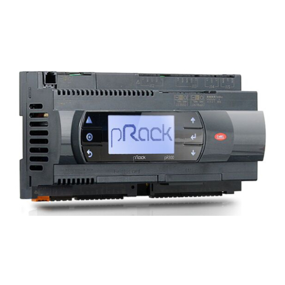
2.1 pRack pR300 S, M, D, L board description
Detailed description of the different pRack pR300 board models and their connectors.
2.2 Technical specifications
Comprehensive technical data including physical and electrical specifications for the pRack pR300.
2.4 pRack pR300 general connection diagram
Visual guide illustrating the electrical connections for various pRack pR300 models.
3. Installation
3.1 General installation instructions
Guidelines for proper installation, including environmental conditions and wiring procedures.
3.2 Power supply
Specifies the correct power supply requirements and connections for the pRack pR300.
3.3 Universal inputs/outputs
Details the functionality and connection of universal inputs/outputs for various sensors.
4. Start Up
4.1 Starting the first time
Step-by-step guide for the initial setup and configuration of the pRack pR300.
5. User Interface
5.1 Graphic terminal
Explains the operation and button functions of the pGD1 graphic terminal.
5.2 Description of the display
Describes the different screen types and their elements on the pRack pR300 display.
5.3 Password
Information on the three password levels (User, Maintenance, Manufacturer) for system access.
6. Functions
6.1 Unit On-Off
Explains how to switch the unit on and off using the terminal, supervisor, or digital input.
6.2 Control
Details the control types, including proportional, P+I, and neutral zone control for system operation.
6.3 Compressors
Covers compressor management, configurations, rotation, and starting procedures.
6.4 Fans
Explains fan control, rotation, and special functions like cut-off and silencer.
6.5 Energy saving
Describes functions for energy saving, such as set point compensation and floating set points.
7. Parameters Table
8. Alarms
8.1 Alarm management
Covers how alarms are managed, acknowledged, and logged within the system.
8.2 Compressor alarms
Details specific alarms related to compressors, including descriptions and actions.
8.3 Pressure and prevent alarms
Explains pressure alarms from switches or probes and high/low pressure prevention functions.
9. Supervisory and Commissioning Systems
9.1 PlantVisor PRO and PlantWatch PRO supervisory systems
Information on connecting to CAREL supervisory systems for monitoring.
9.2 Commissioning software
Guide to using pRack Manager software for configuration, monitoring, and debugging.
10. Updating the Software
10.1 Updating using pRack Manager
Instructions for updating the pRack pR300 software using the pRack Manager PC application.
10.2 Updating using SmartKey
Details on how to update the software using a SmartKey programming key.
10.3 Pendrive: operating instructions
Procedures for uploading and downloading files using a USB pendrive for software updates.
11. Appendix
A.1 System configurations available
Table and diagrams illustrating various available system configurations for pRack pR300.
A.2 Special configurations for subcritical CO2 systems, cascade and pumped systems
Explains specific configurations for CO2 systems, cascade, and pumped applications.
A.4 Alarm table
A comprehensive table listing all alarms, their codes, descriptions, and actions.
A.5 I/O Table
Detailed mapping of all digital and analogue inputs/outputs for the pRack pR300.
Table of Contents
Save PDF
Print
Rename the bookmark
Delete bookmark?
Delete from my manuals?
Login
Sign In
OR
Sign in with Facebook
Sign in with Google
Upload manual
Upload from disk
Upload from URL
Need help?
Do you have a question about the PRK300S3FK and is the answer not in the manual?
Questions and answers