Table of Contents
Advertisement
Quick Links
Advertisement
Table of Contents

Related Manuals for HEIDENHAIN ND 287 - 8-2010


Summary of Contents for HEIDENHAIN ND 287 - 8-2010
- Page 1 Operating Instructions ND 287 English (en) 8/2010...
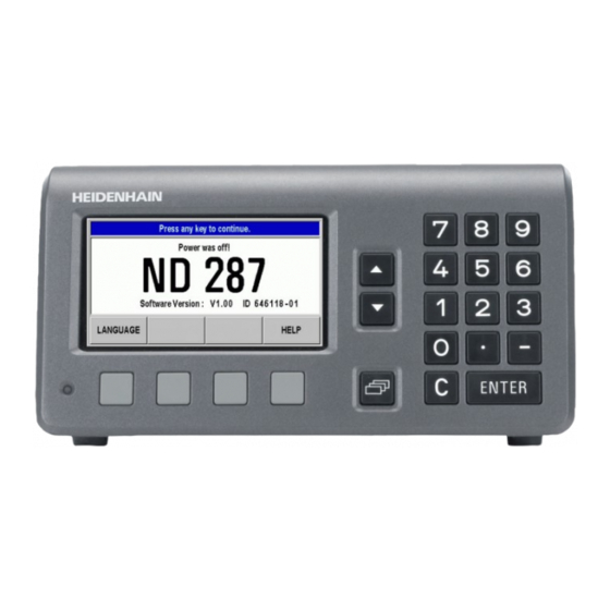
- Page 2 ND 287 Screen ND 287 Front Panel...
- Page 3 Controls and Displays Status bar Current operating mode: Actual Value, Distance-To-Go. Current display mode for input X1, X2 or coupled axes X1:X2. SCL shown in black: Scaling factor is active. COMP shown in black: Error compensation or axis-error compensation is active for the currently displayed axis or coupled axes.
- Page 4 Power switch Power connection with fuse Ground (protective earthing) Encoder module for connecting a HEIDENHAIN encoder with 11 µApp , 1 Vpp or EnDat 2.1/2.2 interface Option: Analog module for connecting an analog sensor Optional: Encoder module for connecting a HEIDENHAIN encoder with 11 µApp , 1 Vpp or EnDat 2.1/2.2 interface ...
- Page 5 Introduction Software version The software version is shown on the power-up screen of the ND 287. This manual describes the functions that are available in the ND 287 and the installation of the units. Symbols within notes Every note is marked with a symbol on the left indicating to the operator the type and/or potential severity of the note.
-
Page 7: Table Of Contents
I Working with the ND 287 Position Display Unit ..13 I – 1 ND 287 Position Display Unit ..14 I – 2 Fundamentals of Positioning ..16 Datums ..16 Actual position, nominal position and distance-to-go ..17 Absolute workpiece positions .. - Page 8 I – 5 Series of Measurements and Statistical Process Control ..42 Functions ..42 Switching between series of measurements and SPC mode ..42 Calling the SERIES OF MEASUREMENTS menu ..43 Analysis of series of measurements ..43 Setting up a series of measurements ..
- Page 9 II Installation, Specifications ..63 II – 1 Installation and Electrical Connection ..64 Items supplied ..64 Optional accessories ..64 Mounting ..65 Environmental conditions ..65 Mounting location ..65 ND 287 – Mounting and installation ..65 Electromagnetic compatibility/ CE compliance ..
- Page 10 Trigger signal for error ..98 Zero crossover ..98 II – 4 Encoder Parameters ..99 Table values ..99 HEIDENHAIN linear encoders ..99 HEIDENHAIN angle encoders ..100 II – 5 Data Interface ..101 Data communication ..101 Serial data transfer with the Import or Export function ..
- Page 11 II – 7 Input and Output of Parameter List and Error Compensation Table ..117 Text file ..117 Output format of the parameter list ..118 First line ..118 Second line ..118 Subsequent lines for the individual parameters ..118 Last line ..
-
Page 13: I Working With The Nd 287 Position Display Unit
Working with the ND 287 Position Display Unit ND 287... -
Page 14: I - 1 Nd 287 Position Display Unit
I – 1 ND 287 Position Display Unit The ND 287 position display unit from HEIDENHAIN is designed for measuring devices, adjustment and testing equipment, automated tasks, as well as infeed and positioning tasks with up to two axes that can be moved manually. - Page 15 Series of measurements: Sorting measured values and finding the Minimum, Maximum, Sum, Difference or a definable coupled position value. Displaying the sorting results in order to intervene, if necessary. Memory capacity for series of measurements: Up to 10 000 ...
-
Page 16: I - 2 Fundamentals Of Positioning
I – 2 Fundamentals of Positioning Datums The workpiece drawing identifies a certain point on the workpiece (usually a corner) as the absolute datum and perhaps one or more other points as relative datums. The datum setting procedure establishes these points as the origin of the absolute or relative coordinate systems. -
Page 17: Actual Position, Nominal Position And Distance-To-Go
Actual position, nominal position and distance-to-go The position of the length gauge at any given moment is called the actual position, while the position that the length gauge is to move to is called the nominal position. The distance from the nominal position to the actual position is called the distance-to-go (see Fig. -
Page 18: Absolute Workpiece Positions
Absolute workpiece positions Each position on the workpiece is uniquely identified by its absolute coordinates (see Fig. I.5). Example: Absolute coordinates of position 1: Z = 20 mm If you are drilling or milling a workpiece according to a workpiece drawing with absolute coordinates, you are moving the tool or length gauge to the value of the coordinates. -
Page 19: Incremental Position Encoders
Incremental position encoders Incremental linear and rotary encoders from HEIDENHAIN convert the movements of, for example, a length gauge into electrical signals. A position display unit, such as the ND 287, constantly evaluates these signals and calculates the actual positions of the length gauge, which it displays as a numerical value on the screen. -
Page 20: Reference Marks
Reference marks Encoders normally contain one or more reference marks (see Fig. I.9) which the ND 287's reference mark evaluation feature uses to re- establish datum positions after a power interruption. There are two main options available for reference marks: fixed and distance-coded. Encoders with distance-coded reference marks have marks separated by a specific encryption pattern that allows the ND 287 to use any two pair of marks along the length of the encoder to re-... -
Page 21: Basic Functions Of The Nd 287
I – 3 Basic Functions of the ND 287 Switching on the ND 287 Switch on the ND 287. The power switch is located on the back of the ND. After switching the ND 287 on, or after a power failure, the power-up screen will appear (see Fig. -
Page 22: Reference Mark Evaluation
Reference mark evaluation The ND 287's REF reference mark evaluation feature automatically re- establishes the relationship between axis-slide or length gauge positions and display values that you last defined by setting the datum. Reference mark evaluation if an incremental encoder is connected (see Fig. -
Page 23: Standard Screen Layout
Standard screen layout In addition to displaying position information, the ND 287 standard screen also displays information on settings and operating modes at any time (see Fig. I.13). The standard screen is divided into the following areas: Status bar Current operating mode: Actual Value, Distance- ... - Page 24 Status display < / = / >: The first three symbols become effective as soon as you activate the tolerance checking and sorting mode as well as during Statistical Process Control (SPC). The symbols are shown in red if the current value is less than the lower sorting limit or greater than the upper sorting limit.
-
Page 25: Soft-Key Functions On The Standard Screen
Soft-key functions on the standard screen There are three pages (rows) of soft-key functions. Use the NAVIGATION key (shown at left) to move through the pages. The page indicator in the status bar shows the number of Fig. I.14 Page indicator pages. - Page 26 Soft key page 3: Soft key Function Page This function is only available if the ND is configured for two Page 27, Page 78 [X2] axes: Switches the display mode in the status bar (X1, X2, X1:X2) and the display value. The upper axis designation indicates the displayed axis, here ...
-
Page 27: Axis Display Mode
Axis display mode Press the X1-X2 [f(X1,X2)] soft key to select the desired display mode and the corresponding display value (see "Soft-key functions on the standard screen" on page 25): Status Bar Function Display mode of axis X1 or input X1 If an analog sensor is connected to ... -
Page 28: Integrated Help System
Integrated help system The integrated help system provides appropriate information and assistance in any situation (see Fig. I.17). To call the integrated help system: Press the HELP soft key. Information relevant to the current operation will be displayed. Use the UP or DOWN arrow keys or the PAGE UP or DOWN soft ... -
Page 29: Data Input Forms
Data input forms Information required for various operational functions and setup parameters is entered through a data input form. These forms will appear after selecting features that require any additional information. Each form provides specific fields for entering the required information. -
Page 30: I - 4 Job Setup
I – 4 Job Setup Operating modes The ND 287 has two operating modes: Actual Value and Distance- To-Go. Status Bar Function Fig. I.19 Actual Value symbol (highlighted) in the status display Shows current actual position Displays current distance from the nominal position In the Actual Value operating mode, the ND 287 always displays the current actual position of the length gauge, relative to the active... -
Page 31: Datum Setting
Datum setting The datum setting procedure assigns the matching display value to a known position. With the ND 287 position display unit, you can set two separate datum points. During operation, you can reset the display value of the axis to zero, or preset it to a defined or new value. -
Page 32: Setting The Display Value For Two Axes In Display Mode X1:X2 (Applies To X1+X2, X1-X2, F(X1,X2))
Setting the display value for two axes in display mode X1:X2 (applies to X1+X2, X1-X2, f(X1,X2)) Select soft-key page 3 on the standard screen. Select display mode X1:X2 (see "Axis display mode" on page 27). If necessary, press the DATUM soft key to select the datum you ... -
Page 33: Calling The Job Setup Menu
Calling the JOB SETUP menu The ND 287 offers two categories for setting up operating parameters: JOB SETUP and INSTALLATION SETUP. The JOB SETUP parameters are used to accommodate specific machining requirements for each job. The INSTALLATION SETUP menu is used to establish encoder, display and communication parameters (see "INSTALLATION SETUP menu"... -
Page 34: Unit Of Measure
Unit of measure The UNITS OF MEASURE form is used to specify the preferred display units and formats for linear and angular measurements. The ND 287 powers up with these settings in effect. In the LINEAR field, define the unit of measure for linear measurement: In the JOB SETUP menu, select UNITS and press the ENTER key to ... -
Page 35: Scaling Factor
Scaling factor The scaling factor may be used to scale the part up or down. All encoder movements are multiplied by the scaling factor. A scaling factor of 1.0 creates a part with the exact size as dimensioned on the print. ... -
Page 36: Value For Datum Point
Value for datum point This form is used to set a value for a datum point (see Fig. I.27). In the JOB SETUP menu, select VALUE FOR DATUM POINT and press the ENTER key to open the form. Enter the value and press ENTER to confirm your entry. ... -
Page 37: Console Adjustment
Console adjustment You can adjust the brightness of the ND 287's LCD display (see Fig. I.29): In the JOB SETUP menu, select CONSOLE ADJUSTMENT and press the ENTER key to open the form. Press the DECREASE or INCREASE soft key to adjust the ... -
Page 38: Switching Signals
Switching signals Danger to internal components! The power supply of external circuits must comply with EN 50178 requirements for low voltage electrical separation. Connect inductive loads only with a quenching diode parallel to the inductance. Danger to internal components! Use only shielded cables and connect the shield to the connector housing. -
Page 39: Measured Value Output
Measured value output With the measured value output feature, the current display values can be transmitted over the serial port. Output of the current display values is activated via a switching signal at D-sub connection X41, the command CTRL B, or the PRINT soft key (see "Measured Value Output"... -
Page 40: Function Of External Inputs
Function of external inputs Danger to internal components! The power supply of external circuits must comply with EN 50178 requirements for low voltage electrical separation. Connect inductive loads only with a quenching diode parallel to the inductance. Danger to internal components! Use only shielded cables and connect the shield to the connector housing. -
Page 41: Compensation Using A Reference Part
Compensation using a reference part Select the REFERENCE PART COMP. menu item to activate temperature compensation using a reference part. Prerequisites: A temperature sensor is connected to encoder input X2. For the temperature sensor, you have set the ENCODER TYPE field in the ENCODER SETUP menu to COMPENSATION and entered the following encoder parameters, see "Setting up the encoder", page 72:... -
Page 42: Series Of Measurements And Statistical Process Control
I – 5 Series of Measurements and Statistical Process Control Functions In addition to displaying measured values, the ND 287 can record and evaluate measured values as a series of measurements, and can perform Statistical Process Control (SPC). You can record series of measurements with up to 10000 measured values per connected axis. -
Page 43: Calling The Series Of Measurements Menu
Calling the SERIES OF MEASUREMENTS menu All parameters required for a series of measurements and the possibility of analyzing a previously recorded series of measurements are provided by the SERIES OF MEASUREMENTS menu. To call the SERIES OF MEASUREMENTS menu, press the MEAS. ... -
Page 44: Setting Up A Series Of Measurements
Setting up a series of measurements To define the parameters of the series of measurements: Call the SERIES OF MEASUREMENTS menu. Select MEAS. SERIES SETUP. In the RECORD MEAS. VALUES field, activate or deactivate measured-value recording for a series of measurements. In the RECORD field, select the trigger for recording the measured ... - Page 45 If you have selected SAMPLING INTERVAL, the two following parameters in the second soft-key row are available for the exact definition of the interval: In the TIME SLOT field, define the duration of the series of measurements in hours/minutes/seconds. Use the soft keys to move from hours to minutes and seconds, and vice versa.
-
Page 46: Defining The Display For A Series Of Measurements
Defining the display for a series of measurements In the SERIES OF MEASUREMENTS menu, select MEAS. SERIES DISPLAY. Then press the DISPLAY MEAS. SER. soft key to select the value to be displayed while a series of measurements is being performed: ACTL DISPLAY: Current measured value is displayed. -
Page 47: Defining The Record Mode
Defining the record mode The ND 287 can record different types of measured values: In the MEAS. SERIES menu, select the RECORD MODE menu item. Press the RECORD MEAS. SERIES soft key to select the mode of recording: ACTL DISPLAY: Current measured value is recorded. -
Page 48: Starting And Stopping A Series Of Measurements
Starting and stopping a series of measurements Select the first soft-key page of the standard screen. Press the START MEAS. SERIES soft key to start a series of measurements. If the START SPC soft key is displayed on the screen, press the SPC [MEAS. -
Page 49: Calling The Spc Menu
Calling the SPC menu All parameters required for Statistical Process Control (SPC) and the possibility of analyzing the current or completed SPC are provided by the SPC menu. To call the SPC menu, press the SPC [MEAS. SERIES] soft key in the ... - Page 50 Press the GRAPH soft key to call a graphic display of all measured values, including the lower tolerance limit LT, upper tolerance limit UT, nominal value (mean tolerance value) NV and the average . The graph shows the last 30 measured values. Use the value soft keys to scroll the graph forward or backward by 25 measured values at a time.
- Page 51 Press the CONTROL CHART s soft key to display the control chart for standard deviation s (s chart). The standard deviation s of each sample is entered in this control chart. The control chart shows up to 30 of the last values. Use the soft keys to scroll the graph forward or backward by 25 measured values at a time.
-
Page 52: Setting Up Spc
Setting up SPC Call the SPC SETUP submenu to define the SPC parameters: Call the SPC menu. Select SPC SETUP. This opens the SPC SETUP submenu. The following parameters for setting up SPC are available: SAMPLES TOLERANCES ... -
Page 53: Tolerances
Tolerances If you edit the values entered, the ND displays a warning. In order to save the changes, the ND must clear the data stored in the FIFO memory.Press the ENTER key to confirm, or press the C key to cancel. In the TOLERANCES form, you define the tolerance limits for statistical process control: In the SPC SETUP submenu, select TOLERANCES and press the... -
Page 54: Control Limits
Control limits Incorrect control limits may increase the statistical spread of the process! If the measured value falls below or exceeds the control limits during statistical process control, the ND 287 displays a warning and switches the display to the respective control chart. -
Page 55: Statistical Distribution
Statistical distribution The STATISTICAL DISTRIBUTION form allows you to define the calculation and graphic display of the distribution density curve in the histogram: In the SPC SETUP submenu, select STATISTICAL DISTRIBUTION and press the ENTER key to open the form. Press the DISTRIBUTION soft key to select the type of statistical ... -
Page 56: Deleting Spc Statistics
Deleting SPC statistics Use DELETE STATISTIC to delete all measured values stored in memory and to restart statistical process control: Call the SPC menu. Select DELETE STATISTIC and press the ENTER key to confirm, or press the C key to cancel. If you press ENTER, the ND will clear all recorded measured values from the FIFO memory. - Page 57 The measured values and the data of the diagrams and control charts always apply to the currently active display mode (see "Axis display mode" on page 27): In display mode X1, the SPC data applies to the encoder at input X1. In display mode X2, the SPC data applies to the ...
-
Page 58: I - 6 Sorting And Tolerance Checking
I – 6 Sorting and Tolerance Checking Sorting function To sort the parts, the ND 287 compares the displayed value with an upper or lower sorting limit, and displays the sorting result in color as a display value and with the appropriate sorting symbol in the status display: Green symbol: = ... -
Page 59: Defining The Sorting Parameters
Defining the sorting parameters Select the first soft-key page of the standard screen. Press the TOLERANCE CHECKING soft key to open the SORTING AND TOLERANCE CHECKING menu. In the SORTING field, press the ON/OFF soft key to activate or ... -
Page 60: I - 7 Error Messages
I – 7 Error messages Overview Various error messages may occur while you're using the ND 287. The ND 287 always stores the last error of each error category. You can acknowledge the error messages by pressing the C key, or by applying an external signal to pin 2 of the D-sub connection X41. - Page 61 Error message Error cause and corrective action A sample has violated the upper or lower control limit during analysis. Check the Violation of control limits respective control chart and change the process settings, if required. When this error occurs, error pin 19 is not activated, but the ND automatically switches to the control chart that caused the error.
- Page 62 I Working with the ND 287 Position Display Unit...
-
Page 63: Installation, Specifications
Installation, Specifications ND 287... -
Page 64: Installation And Electrical Connection
Items supplied ND 287 position display unit with the following connections: An encoder module for connecting a HEIDENHAIN encoder with 11 µApp, 1 Vpp or EnDat 2.1/2.2 interface for axis X1 is a standard item supplied with the position display unit. -
Page 65: Mounting
Mounting Environmental conditions Property Value Protection (IEC 60529) IP 40 rear panel IP 54 front panel Operating temperature 0° to 50 °C (32° to 122 °F) Storage temperature –40 ° to 85 °C (–40 ° to 185 °F) Relative air humidity Annual mean: <... -
Page 66: Electromagnetic Compatibility/Ce Compliance
Electromagnetic compatibility/ CE compliance The ND 287 fulfills the requirements for electromagnetic compatibility according to 2004/108/EC with respect to the generic standards for Noise immunity as per IEC 61000-6-2: Specifically: ESD as per IEC 61000-4-2 Electromagnetic fields as per IEC 61000-4-3 ... -
Page 67: Electrical Connection
Electrical connection Electrical requirements Danger of electrical shock! Unplug the power cord before opening the housing. Connect a protective ground (see "Grounding" on page 67). The protective ground connection must never be interrupted. Danger to internal components! Do not engage or disengage any connections while the unit is under power. -
Page 68: Preventative Maintenance Or Repair
Preventative maintenance or repair No special preventative maintenance is necessary. For cleaning, wipe lightly with a dry lint-free cloth. Danger of electrical shock! The position display unit must be repaired by qualified and authorized service technicians. See the last page of the Operating Instructions for our ... -
Page 69: Optional: Analog Module With ±10-V Interface At Input X1 Or X2 For Connecting An Analog Sensor
Pin assignment X1/X2 D-sub Input signal Input signal connector EnDat 2.1/2.2 11 µApp 1 Vpp 15-pin 0 V (UN) 0 V (UN) 0 V (UN) 5 V (Up) 5 V (Up) 5 V (Up) Data Internal shield I0– R– Fig. II.6 15-pin encoder connector X1 or X2 for the encoder input on the rear panel Clock... -
Page 70: Ii - 2 Installation Setup
II – 2 Installation Setup INSTALLATION SETUP menu The ND 287 offers two categories for setting up operating parameters: JOB SETUP and INSTALLATION SETUP. The JOB SETUP parameters are used to accommodate specific machining requirements for each job, see "Job Setup" on page 30. ... - Page 71 When in the INSTALLATION SETUP menu, the following soft keys will be available (see Fig. II.7): JOB SETUP Press to begin accessing the JOB SETUP parameters (see "Job Setup" on page 30). IMPORT/EXPORT Press this soft key to call the IMPORT or EXPORT soft keys for transmitting the operating parameters (see "Serial data transfer with the Import or Export function"...
-
Page 72: Setting Up The Encoder
Setting up the encoder In the ENCODER SETUP form you configure the ND 287 for the connected encoder: The cursor will default to the ENCODER SETUP field upon opening Installation Setup. Press the ENTER key to confirm your selection. If you have configured the ND for two axes in the APPLICATION ... -
Page 73: Incremental Linear Encoder
Incremental linear encoder For linear encoders, cursor to the SIGNAL PERIOD field and toggle the COARSER or FINER soft key to select a predefined encoder signal period, or type in the exact signal period (in µm) desired (see "Encoder Parameters" on page 99). In the REFERENCE MARK field, toggle the REF MARK soft key to ... -
Page 74: Incremental Angle Encoder
Incremental angle encoder For rotary encoders, enter the encoder's signal period per revolution (360°) directly in the SIGNAL PERIOD field (see "Encoder Parameters" on page 99). Press the DOWN arrow key to move to the next parameter. In the REFERENCE MARK field, use the numeric keys to enter the ... -
Page 75: Absolute Encoder
Absolute encoder For absolute encoders with EnDat 2.1/2.2 interface, you can only define the COUNT DIRECTION and the ERROR MONITOR. All other fields in the ENCODER SETUP form show information that has been transferred from the encoder. Press the ENDAT ENC. FILE soft key to display the encoder's electronic ID label. -
Page 76: Analog Sensor With ±10 V Interface, Preferably A Temperature Sensor
Analog sensor with ±10 V interface, preferably a temperature sensor In the COUNT DIRECTION field, select the count direction by pressing the POSITIVE/ NEGATIVE soft key. If the encoder's count direction matches the user's traverse direction, select POSITIVE. If the directions do not match, select NEGATIVE. -
Page 77: Configuring The Display
Configuring the display In the DISPLAY CONFIGURATION form you determine the display resolution for the different encoders. In the INSTALLATION SETUP menu, select DISPLAY CONFIGURATION. If you have configured the ND for two axes in the APPLICATION field under COUNTER SETTINGS, a list of of the two possible encoder inputs, labelled INPUT X1 and X2, appears. -
Page 78: Counter Settings
Counter settings In the COUNTER SETTINGS form, you define the user application for the position display unit (see Fig. II.23): In the INSTALLATION SETUP menu, select COUNTER SETTINGS. In the APPLICATION field, press the 1 AXIS/2 AXES soft key to ... -
Page 79: Formula For Coupled Position
Formula for coupled position In this form, you can enter a formula for coupling the two axes. The following mathematical operations, symbols and variables are available: Basic arithmetic: Addition, subtraction, multiplication and division Parentheses Trigonometric functions: Sine, cosine, tangent, arc sine, arc cosine ... -
Page 80: Error Compensation
This error can either be linear or non-linear. You can determine these errors with a reference measurement system, e.g. the VM 101 from HEIDENHAIN. From an analysis of the error it can be determined which form of compensation is required (linear or non-linear). -
Page 81: Linear Error Compensation (Not For Rotary Encoders)
Linear error compensation (not for rotary encoders) Linear error compensation can be applied if the results of the comparison with a reference standard show a linear deviation over the whole measuring length. In this case the ND 287 can compensate the error mathematically by calculating the LEC correction factor. -
Page 82: Non-Linear Error Compensation
Non-linear error compensation Non-linear error compensation is available for encoders with reference marks, for absolute encoders and for analog sensors. If non-linear error compensation has been defined, no error compensation will be applied until the reference marks have been crossed. Non-linear error compensation should be applied if the results of the comparison with a reference standard show an alternating or oscillating deviation. - Page 83 Creating an error compensation table To start a new error compensation table, first press the EDIT TABLE soft key. This opens the ERROR COMPENSATION TABLE form. It may occur that the error is not caused by the axis to be ...
- Page 84 Configuring an error compensation table Press the EDIT TABLE soft key to view the table entries. Use the UP or DOWN ARROW keys or the numeric keys to move the cursor to the correction point to be added or changed. Press ENTER to confirm your selection.
- Page 85 The error compensation table data may be saved to or loaded from a PC via the serial port (see "Setting up the serial port" on page 86). Exporting the current compensation table Press the EDIT TABLE soft key. Press the IMPORT/EXPORT soft key. ...
-
Page 86: Setting Up The Serial Port
Setting up the serial port The ND 287 features two serial interfaces: RS-232-C/V.24 (X31) and USB (UART, X32). Danger of electrical shock! The interfaces X31 and X32 comply with the requirements of EN 50 178 for low voltage electrical separation. Do not engage or disengage any connections while the unit is under power. - Page 87 Press the 7/8 soft key to set the DATA BITS field to 7 or 8. Press the 1/2 soft key to set the STOP BITS field to 1 or 2: The PARITY field can be set to NONE, EVEN or ODD using the soft ...
-
Page 88: Diagnostics
Diagnostics The DIAGNOSTICS submenu provides parameters for testing the keypad, the LCD display, the connected encoders, the supply voltages, and the function of the switching inputs/outputs (see Fig. II.43): In the INSTALLATION SETUP menu, select DIAGNOSTICS. Select the desired test. The tests are described in the following ... -
Page 89: Encoder Test
Encoder test Use this test to check the signals of the 11 µApp or 1 Vpp interface, the EnDat 2.1/2.2 interface or the voltage at the analog module. If you have configured the ND for two axes in the APPLICATION ... - Page 90 Encoders with EnDat 2.1/2.2 interface: The form displays the electronic ID label of the connected encoder: Transmission format, signal periods, measuring steps, distinguishable revolutions, ID number and serial number. Only for encoders with EnDat 2.2 interface: The DIAGNOSIS soft ...
-
Page 91: Power Supply
Analog sensors with ±10 V interface: In the form, the voltage at the input of the analog module is displayed as a numerical value and in a bar graph. Power supply Check the supply voltage at encoder inputs X1 and X2 (optional). It should normally be slightly above 5 V in order to ensure that the voltage level at the encoder input complies with the specification (5 V ±... -
Page 92: Switching Inputs Test
Switching inputs test Danger to internal components! The power supply of external circuits must comply with EN 50178 requirements for low voltage electrical separation. Connect inductive loads only with a quenching diode parallel to the inductance. Danger to internal components! Use only shielded cables and connect the shield to the connector housing. -
Page 93: Switching Outputs Test
Switching outputs test Danger to internal components! The power supply of external circuits must comply with EN 50178 requirements for low voltage electrical separation. Connect inductive loads only with a quenching diode parallel to the inductance. Danger to internal components! Use only shielded cables and connect the shield to the connector housing. -
Page 94: Ii - 3 Switching Inputs And Outputs
II – 3 Switching Inputs and Outputs Switching inputs at D-sub connection X41 Danger to internal components! The power supply of external circuits must comply with EN 50178 requirements for low voltage electrical separation. Connect inductive loads only with a quenching diode ... -
Page 95: Input Signals
Special case: If you want to display the current measured value ACTL of a measurement series, the following applies for inputs 7, 8 and 9: Either none or more than one of these inputs must be active. Input signals Signal Value Internal pull-up resistor active Low... -
Page 96: Switching Outputs At D-Sub Connection X41
Switching outputs at D-sub connection X41 Danger to internal components! The power supply of external circuits must comply with EN 50178 requirements for low voltage electrical separation. Connect inductive loads only with a quenching diode parallel to the inductance. Danger to internal components! Use only shielded cables and connect the shield to the connector housing. -
Page 97: Trigger Limits
Trigger limits As soon as the trigger limit defined by parameter is reached (see figure at right), the corresponding output is activated (3: path). You can set up to two trigger limits: A1 and A2 (see "Switching signals" on page 38). A separate output is available for the zero crossover (see "Zero crossover"... -
Page 98: Sorting Limits
Sorting limits If the measured value exceeds the sorting limits, the ND activates the outputs at pin 17 or pin 18 (see "Sorting and Tolerance Checking" on page 58). Example: See figure at upper right. 1: Lower limit 2: Upper limit ... -
Page 99: Ii - 4 Encoder Parameters
II – 4 Encoder Parameters Table values The following tables represent a partial list of HEIDENHAIN encoders. These tables describe the operating parameters which you must set for the encoders. Most entries can be found in the operating instructions for your encoder. -
Page 100: Heidenhain Angle Encoders
HEIDENHAIN angle encoders Encoder Signal period Reference marks ROD 48x 1000 ... 5000 Single ERN x80 ROC 425 Self-configuring None ECN x25 Absolute ROQ 437 Self-configuring None EQN 437 Absolute ROD 280 18000 Single ROD 280C Coded/36 RON 28x 18000... -
Page 101: Ii - 5 Data Interface
II – 5 Data Interface Data communication The ND 287 features two serial interfaces: RS-232/V.24 (X31) and USB (UART, X32). Danger to internal components! The interfaces X31 and X32 comply with the requirements of EN 50 178 for low voltage electrical separation. Do not engage or disengage any connections while the unit is under power. -
Page 102: Serial Data Transfer With The Import Or Export Function
HyperTerminal, which is included with Windows ®, or TNCremoNT. TNCremoNT is available from HEIDENHAIN free of charge. You will find the software on the HEIDENHAIN web site at www.heidenhain.de on the downloads page underServices and Documentation. -
Page 103: Importing Data Into The Nd 287 From A Pc
To export data from the ND 287 to a PC, the PC must first be made ready to receive the data to save it to a file. Set up the terminal communication program to capture ASCII text data from the COM port to a file on the PC. -
Page 104: Software Update (Firmware Update) Installation
Software update (firmware update) installation If required, you can download a software update (firmware update) for your ND from the HEIDENHAIN web site. You will find the update at www.heidenhain.de on the downloads page under Services and Documentation. To install the software update (firmware update): Connect your PC to the serial port USB Type B (UART, X32), see ... -
Page 105: Wiring The Connecting Cable
Wiring the connecting cable The wiring of the connecting cable depends on the device being connected (see technical documentation for external device). Complete wiring of RS-232-C/V.24 (X31) Before the ND 287 and your PC can communicate, they need to be connected to each other with a serial cable. -
Page 106: Usb Type B (Uart), Socket As Per Iec 61076-3-108
USB driver. You will find the driver file for Windows 2000, XP and Vista in the installation directory of the TNCremo software or on the HEIDENHAIN web site at www.heidenhain.de on the downloads page under Services and Documentation. -
Page 107: External Operation Via Rs-232-C/V. 24 Or Usb Interface
External operation via RS-232-C/V. 24 or USB interface Key commands You can operate the ND 287 remotely over the RS-232-C/V.24 (X31) or USB (UART, X32) data interface using an external device. The following key commands are available: Format <ESC>TXXXX<CR> Key is pressed <ESC>AXXXX<CR>... -
Page 108: Description Of Key Commands
Sequence of commands Function <ESC>T0110<CR> Key 'Soft key 4' (right) Sequence of commands Function <ESC>A0000<CR> Output of device identification <ESC>A0100<CR> Output of position display value <ESC>A0200<CR> Output of actual position <ESC>A0301<CR> Output of error message <ESC>A0400<CR> Output of software ID number <ESC>A0800<CR>... -
Page 109: Key Is Pressed (Txxxx Commands)
Key is pressed (TXXXX commands) The ND acknowledges every correctly received key command by transmitting the control character ACK (Acknowledge, CTRL F). Then the ND executes the key command. The ND responds to commands that cannot be identified or to ... - Page 110 Output of current position: <STX> <CR> <LF> STX control character: 1 character Current position: 10 characters, without decimal point, with leading zeros End of line: 2 characters Output of error message The error text displayed in the message line is ...
- Page 111 Output of status bar: <STX> <CR> <LF> STX control character: 1 character Parameter values of the status bar: 8 characters End of line: 2 characters Column Parameter Operating mode 0 = Actual Value 1 = Distance- To-Go Display mode for 0 = X1 1 = X2 2 = X1 + X2...
- Page 112 Output of status indicators <STX> <CR> <LF> g h i STX control character: 1 character Parameter values of the status display: 10 characters End of line: 2 characters The ND sends the status of the symbols in the status display: 0 = Symbol not active (gray) 1 = Symbol active (red) 2 = Symbol flashing...
-
Page 113: Execute Function (Fxxxx Commands)
Execute function (FXXXX commands) The ND acknowledges every correctly received key command by transmitting the control character ACK (Acknowledge, CTRL F). Then the ND executes the key command. The ND responds to commands that cannot be identified or to ... -
Page 114: Measured Value Output
II – 6 Measured Value Output Alternatives for starting measured value output With a PC, there are three different ways to start measured value output from the ND 287: After a trigger signal at input X41 (see "Switching inputs at D-sub connection X41"... -
Page 115: Measured-Value Output Via The Serial Data Interface X31 Or X32
(e. g. HyperTerminal, which is included with Windows ®). 110 PRINT X$; You can also use the TNCremoNT software. TNCremoNT is 120 GOTO 50 available from HEIDENHAIN free of charge. You will find the 130 END software at www.heidenhain.de on the downloads page under Services and Documentation. -
Page 116: Duration Of Measured Value Transfer
Duration of measured value transfer 11 L --------------------------- - Duration of measured value transfer in [s] Number of blank lines B: Baud rate Example: Data sequence during measured-value output Measured value: X = –5.23 mm The measured value is within the sorting limits (=) and is the current value (A) of a series of measurements. -
Page 117: Input And Output Of Parameter List And Error Compensation Table
To export or import data between the ND 287 and a PC, the PC must use terminal communications software, such as HyperTerminal, which is included with Windows ®, or TNCremoNT. TNCremoNT is available from HEIDENHAIN free of charge. You will find the software at www.heidenhain.de on the downloads page under Services and Documentation. -
Page 118: Output Format Of The Parameter List
Output format of the parameter list First line Each parameter list output begins with the start character < # > (HEX: 0x23). <CR> <LF> Start character and end of line: 3 characters Second line Model of position display unit and unit of measure D E G <CR>... -
Page 119: Examples For Parameter Lists
Examples for parameter lists The parameter text is always sent in English. The parameter value, not the text, is definitive when the parameters are transferred to the ND. The values in boldface type are the default settings. ND 287 with rotary encoder connected to input X1 Parameter Meaning Start character (#) - Page 120 Parameter Meaning LIN. COMP. = Linear compensation: 0.0 µm/m (default setting) ANALOG U1 = 10.000 Analog module: Voltage 1 = 10.000 V (default setting) ANALOG U2 = 10.000 Analog module: Voltage 2 = –10.000 V (default setting) ANALOG.POS1 = 10.0000 Analog module: Position 1 (10.000 is the default setting) ANALOG.POS2 = 10.0000...
- Page 121 Parameter Meaning TIME SEC = Time slot for measurement series in seconds: 5 s, 0 s is the default setting TIME MIN = Time slot for measurements series in minutes: 0 min is the default setting TIME H = Time slot for measurement series in hours: 0 h is the default setting INTERVALL = Sampling interval for measurement series: 20 ms - 10 sec, 0 ms is the default setting...
-
Page 122: Nd 287 With Two Rotary Encoders Connected To Inputs X1 And X2 (Optional)
ND 287 with two rotary encoders connected to inputs X1 and X2 (optional) Parameter Meaning Start character (#) ND-287 2 Model: ND-287, Unit of measure: DEG, DMS or rad LINEAR = Unit of measure for linear dimensions: mm = 0, inches = 1 ANGULAR = Unit of measure for angular dimensions: DEG = 0, DMS = 1, rad = 2 P03.1... - Page 123 Parameter Meaning P34.2 DP PLACES = X2: Decimal places: 4 (default setting) P35.1 REF ON/OFF = X1: Reference mark: 0 = off, 1 = on P35.2 REF ON/OFF = X2: Reference mark: 0 = off, 1 = on P36.1 REF MARK = X1: 0 = single reference mark, 1..6: coded reference marks P36.2 REF MARK =...
- Page 124 Parameter Meaning BLANK LINE = Blank lines: 1 (0 - 99) DISP.FREEZE = Display freeze: 0 = current, 1 = frozen, 2 = stopped PRESET = 0.0000 Value for preset via external signal: 0.0000 A1 ON/OFF = Switching output A1: 0 = off, 1 = on A2 ON/OFF = Switching output A2: 0 = off, 1 = on LIMIT A1 =...
- Page 125 Parameter Meaning LCL-X = 0.0000 Value for lower control limit (SPC: X control chart): 0.0000 is the default setting UCL-S = 0.0000 Value for upper control limit (SPC: S control chart): 0.0000 is the default setting UCL-R = 0.0000 Value for upper control limit (SPC: R control chart): 0.0000 is the default setting LANGUAGE = National language: 0 - 9, 0 = English...
-
Page 126: Output Format Of The Error Compensation Table
Output format of the error compensation table The ND outputs a separate error compensation table for each axis to be compensated. First line Each error compensation table output begins with the start character < # > (HEX: 0x23). <CR> <LF> Start character and end of line: 3 characters Second line Model of position display unit and unit of measure... -
Page 127: Fourth Line (Only If Second Axis Input Is Available, Optional)
Fourth line (only if second axis input is available, optional) Output of error-causing axis <CR> <LF> Error-causing axis, left-aligned: 13 characters Separator block: 3 characters Axis value, right-aligned: 6 characters End of line: 2 characters Fifth line Output of compensation point spacing (only for linear encoders): S P A C I <CR>... -
Page 128: Seventh Line
Seventh line Output of compensation value no. 0: C O M P . <CR> <LF> Compensation number zero, left-aligned: 13 characters Separator block: 3 characters Compensation position zero, right-aligned: 13 characters Separator block: 3 characters Compensation value zero, right-aligned: 13 characters End of line: 2 characters Subsequent lines for further compensation values Output of compensation values 1 - 199 for linear measurements (1 -... -
Page 129: Examples Of Error Compensation Tables
Examples of error compensation tables ND 287 with linear encoder connected to input X1 Parameter Meaning Start character (#) ND-287 1 Model: ND-287, unit of measure MM or IN (inches) AXIS X1 Axis to be compensated SPACING 10.0000 Point spacing: 10 mm (value input) DATUM 0.0000 Datum: 0 mm (value input) - Page 130 Parameter Meaning COMP.NO. 191 + 1910.0000 = COMP.NO. 192 + 1920.0000 = COMP.NO. 193 + 1930.0000 = COMP.NO. 194 + 1940.0000 = COMP.NO. 195 + 1950.0000 = COMP.NO. 196 + 1960.0000 = COMP.NO. 197 + 1970.0000 = COMP.NO. 198 + 1980.0000 = COMP.NO.
-
Page 131: Nd 287 With Two Linear Encoders Connected To Inputs X1 And X2 (Optional)
ND 287 with two linear encoders connected to inputs X1 and X2 (optional) Parameter Meaning Start character (#) ND-287 2 Model: ND-287, unit of measure MM or IN (inches) AXIS X1 Axis to be compensated X1 FCT X1 Error-causing axis SPACING X1 10.0000 Point spacing: 10 mm (value input) - Page 132 Parameter Meaning COMP.NO. 192 + 1920.0000 = COMP.NO. 193 + 1930.0000 = COMP.NO. 194 + 1940.0000 = COMP.NO. 195 + 1950.0000 = COMP.NO. 196 + 1960.0000 = COMP.NO. 197 + 1970.0000 = COMP.NO. 198 + 1980.0000 = COMP.NO. 199 + 1990.0000 = Final character (#) II Installation, Specifications...
-
Page 133: Nd 287 With Rotary Encoder Connected To Input X1
ND 287 with rotary encoder connected to input X1 The compensation points have a fixed spacing of two degrees relative to each other. Parameter Meaning Start character (#) ND-287 1 Model: ND-287, Unit of measure: DEG, DMS or rad AXIS X1 Axis to be compensated COMP.NO. - Page 134 Parameter Meaning COMP.NO. 176 352.0000 COMP.NO. 177 354.0000 COMP.NO. 178 356.0000 COMP.NO. 179 358.0000 Final character (#) II Installation, Specifications...
-
Page 135: Ii - 8 Specifications
, input frequency max. 100 kHz Sinusoidal signals 11 V , input frequency max. 500 kHz Absolute HEIDENHAIN encoders with EnDat 2.1/2.2 interface Possible signal periods for linear and rotary encoders: For rotary encoders: 1 - 999 999.999 ... - Page 136 Specifications Multilingual user guidance Functions REF reference-mark evaluation for distance-coded or single reference marks Display for lengths, angles, or optionally for other measured values from analog sensors Distance-To-Go or Actual Value operating mode Two datums Scaling factor ...
- Page 137 USB Type B (UART) You can use only one interface for data transfer at a time. The data transfer software TNCremoNT is available for free on the HEIDENHAIN web site at www.heidenhain.de on the downloads page under Services and Documentation.
-
Page 138: Ii - 9 Dimensions
II – 9 Dimensions ND 287 Dimensions in mm HEIDENHAIN Front view with dimensions Side view with dimensions Dimensions in mm Tolerancing ISO 8015 ISO 2768 - m H ± < 6 mm: 0.2 mm Bottom view with dimensions II Installation, Specifications... -
Page 139: Ii - 10 Accessories
II – 10 Accessories ID numbers for accessories ID number Accessories 654017-01 Encoder module, packaged 654018-01 Analog module, packaged 654019-01 Ethernet module, packaged 654020-01 Mounting base for installation in a 19-inch electrical cabinet, packaged 366964-xx Data transfer cable for RS-232-C/V.24 interface, packaged 354770-xx Data transfer cable for USB interface,... -
Page 140: Mounting The Input Assemblies
Disengage the power plug before opening the unit! An encoder module for connecting a HEIDENHAIN encoder with 11µApp, 1 Vpp or EnDat 2.1/2.2 interface for axis X1 is a standard item supplied with the position display unit. As an option, you can replace this module by an analog module. -
Page 141: Mounting Base For Installation In 19-Inch Electrical Cabinet
Mounting base for installation in 19-inch electrical cabinet ID number 654020-01 Dimensions (mm) HEIDENHAIN Front view with dimensions Side view with dimensions Dimensions in mm 3-D view, secure the mounting base with two M4 x 6 screws to the electrical cabinet. - Page 142 II Installation, Specifications...
- Page 143 Incremental angle encoder ... 74 Integrated help system ... 28 Angle encoders from Incremental linear encoder ... 73 Interface, setting up..86 HEIDENHAIN ... 100 Encoders, connecting the ..68 Items supplied ... 64 Environmental conditions ... 65 Error compensation ... 80 Basic functions ...
- Page 144 Standard screen ... 23 Statistical process control ... 42 Parameter list Analysis ... 49 Example ... 119 Control limits ... 54 Input and output ... 117 Delete statistic ... 56 Output format ... 118 Measured value recording ... 55 Passcode ... 70 Menu, calling the ...
- Page 145 Ve 01 662 206-21 · pdf · 11/2010...
Need help?
Do you have a question about the ND 287 - 8-2010 and is the answer not in the manual?
Questions and answers