Table of Contents
Advertisement
Advertisement
Table of Contents

Related Manuals for HEIDENHAIN ND 522 - 2-2011


Summary of Contents for HEIDENHAIN ND 522 - 2-2011
- Page 1 User’s Manual ND 522/523 English (en) 2/2011...
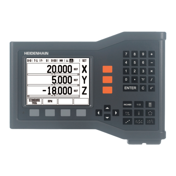
- Page 2 ND 522/523 Screen View of the ND 522/523 screen defining typical information provided. Datum Tools Feed Rate Stopwatch Unit of Measure Actual Value Distance-To-Go Page Indicator Set/Zero Axis Label Ref Symbol Soft Key Functions Graphic Positioning Aid Display Area ND 522/523 Front Panel View of the ND 522/523 front panel defining keys, and features.
- Page 3 ND 522/523 Back Panel Main power input Power switch Grounding Edge Finder KT 130 Edge Finder Ground (Protective Earthing) Serial Port Axis ports ND 522/523...
- Page 5 Introduction Software Version The software version is shown on the initial power up screen. This User's Manual covers the functions of the ND 522/523 for both milling, and turning applications. Operational information is arranged in three sections: General Operations, Mill Specific Operations, and Turn Specific Operations.
- Page 6 ND 522/523 Fonts The chart below shows how the different variables (soft keys, hard keys) are represented within the text of this manual: Soft keys - SETUP soft key Hard keys - ENTER hard key...
-
Page 7: Table Of Contents
I Operating Instructions ..11 I - 1 Fundamentals of Positioning ..12 Datums ..12 Actual Position, Nominal Position, and Distance-To-Go ..12 Absolute Workpiece Positions ..13 Incremental Workpiece Positions ..13 Zero Angle Reference Axis ..14 Position Encoders .. - Page 8 I - 3 Milling Specific Operations ..31 Key Functions Detailed ..31 Tool Hard Key ..31 Import/Export ..31 Tool Radius Compensation feature ..32 Tool Length ..32 Sign for the length difference L ..32 Entering tool data ..32 Tool Table Usage ..
- Page 9 II Technical Information ..69 II - 1 Installation, and Electrical Connection ..70 Items Supplied ..70 Accessories ..70 ND 522/523 Display Unit ..70 Mounting Location ..70 Installation ..70 Electrical connection ..70 Electrical requirements ..71 Environmental ..
- Page 10 II - 3 Encoder Parameters ..79 Example settings for HEIDENHAIN linear encoders ..79 Example settings for HEIDENHAIN Rotary encoders ..79 Example settings for HEIDENHAIN Angle encoders ..79 II - 4 Data Interface ..80 USB Port (type “B”) ..81 External Operations via USB port ..
-
Page 11: I Operating Instructions
Operating Instructions ND 522/523... -
Page 12: I - 1 Fundamentals Of Positioning
I - 1 Fundamentals of Positioning Datums The workpiece drawing identifies a certain point on the workpiece (usually a corner) as the absolute datum, and perhaps one, or more other points as relative datums. The datum setting procedure establishes these points as the origin of the absolute, or relative coordinate systems. -
Page 13: Absolute Workpiece Positions
Absolute Workpiece Positions Each position on the workpiece is uniquely identified by its absolute coordinates. Example: Absolute coordinates of position 1: X = 20 mm Y = 10 mm Z = 15 mm When drilling, or milling a workpiece according to a workpiece drawing with absolute coordinates, the tool is moving the value of the coordinates. -
Page 14: Zero Angle Reference Axis
Zero Angle Reference Axis The Zero Angle Reference Axis is the 0 degree position. It is defined as one of the two axes in the plane of rotation. The following table defines the Zero Angle where the position of the angle is zero for the three possible planes of rotation. -
Page 15: Encoder Reference Marks
Encoder Reference Marks Encoders normally contain one, or more reference marks which the ND 522/523’s Reference Mark Evaluation feature uses to re-establish datum positions after a power interruption. There are two main options available for reference marks; fixed, and distance-coded. Encoders with distance-coded reference marks have marks separated by a specific encryption pattern that allows the ND 522/523 to use any two pair of marks along the length of the encoder to re-... -
Page 16: General Operations For Nd 522/523
I - 2 General Operations for ND 522/523 Screen Layout Status Bar Symbols Datum Tool Feed Rate Job Clock Unit of Measure Operating Modes Page Indicator Set/Zero Axis Labels Ref Symbol Soft key Labels Display Area Near Zero Warning (In Distance-To-Go mode only) The ND 522/523 readout provides application-specific features that allows the most productivity be obtained from manual machine tools. -
Page 17: General Operation Hard Key Function Overview
General Operation Hard Key Function Overview The following is a list of Hard keys, and a description of their function which are located on the front panel of the readout. Hard Key Hard Key function Hard key Page 1 Symbol INCREMENTAL Switches display between /ABSOLUTE... -
Page 18: General Navigation
General Navigation Use keypad to enter numeric values within each field. The ENTER key will confirm the entry within a field, and return to the previous screen. Press the C key to clear entries, and error messages, or return back to the previous screen. -
Page 19: Graphic Positioning Aid
Graphic Positioning Aid When traversing to display value zero (in the incremental mode), ND 522/523 displays a graphic positioning aid. ND 522/523 displays the graphic positioning aid in a narrow rectangle underneath the currently active axis. Two triangular marks in the center of the rectangle symbolize the nominal position to be reached. -
Page 20: Data Input Forms
Data Input Forms Information required for various operational functions, and setup parameters are entered through a data input form. These forms will appear after selecting features that require any additional information. Each form provides specific fields for entering the required information. -
Page 21: Power Up
Power Up Switch on the power (located on the back). The initial screen will appear. This screen will only appear the very first time the unit is powered up. The following steps may have already been completed by the installer. Select the proper language by pressing the LANGUAGE soft key. -
Page 22: Enable/Disable Ref Function
ENABLE/DISABLE REF function The toggling ENABLE/DISABLE soft key, that is present during the Reference Mark Evaluation routine, allows the operator to select a specific Reference Mark on an encoder. This is important when using encoders with Fixed Reference Marks. When the DISABLE REF soft key is pressed, the evaluation routine is paused, and any reference marks that are crossed during encoder movement are ignored. -
Page 23: Setup
Setup ND 522/523 offers two categories for setting up operating parameters. These categories are: Job Setup, and Installation Setup. The Job Setup parameters are used to accommodate specific machining requirements for each job. Installation Setup is used to establish encoder, and display parameters. The Job Setup menu is accessed by pressing the SETUP soft key. -
Page 24: Scale Factor
Scale Factor The scale factor may be used to scale the part up, or down. All encoder movements are multiplied by the scale factor. A scale factor of 1.0 creates a part with the exact size as dimensioned on the print. The numeric keys are used to enter a number greater than zero. -
Page 25: Graphic Positioning Aid
Graphic Positioning Aid The GRAPHIC POSITIONING AID form is used to configure the bar graph that is shown below the axes’ display in Incremental mode. Each axis has its own range. Press the ON/OFF soft key to enable, or simply begin entering values using the numeric keys. -
Page 26: Console Adjustment
Console Adjustment The LCD’s contrast can be adjusted either by using the soft keys in this form, or by using the Up/Down arrow keys on the keypad in either operating mode. The contrast may need to be adjusted due to variations in ambient lighting, and operator preference. -
Page 27: Dro Operating Screen Soft Key Function Overview
DRO Operating Screen Soft Key Function Overview There are two pages of soft key functions in the operating screen to select from. Use the LEFT/RIGHT ARROW keys to cursor through each page. The page indicator in the Status bar will show the page orientation. -
Page 28: General Operation Key Functions Detailed
General Operation Key Functions Detailed This section details the soft key functions that are the same, whether the ND 522/523 is configured for Mill, or Turn applications. Set Zero Soft Key The SET/ZERO soft key is a key that determines the effect of pressing an Axis key. -
Page 29: 1/2 Hard Key
1/2 Hard key The 1/2 hard key is used to find the half-way (or midpoint) between two locations along a selected axis of a workpiece. This can be performed in either Incremental, or Absolute mode. This feature will change datum locations when in Absolute mode. -
Page 30: Calc Hard Key
Calc Hard key ND 522/523’s calculator is capable of handling everything from simple arithmetic to complex trigonometry, and RPM calculations. Press the CALC hard key to access the STANDARD/TRIG, and RPM soft keys. When more than one calculation is entered into a numeric field, the calculator will perform multiplication, and division before it performs addition, and subtraction. -
Page 31: I - 3 Milling Specific Operations
I - 3 Milling Specific Operations This section discusses operations, and soft key functions specific to milling applications only. Soft key functions that are the same, whether the ND 522/523 is configured for Mill, or Turn applications, are detailed starting on page 17. Key Functions Detailed Tool Hard Key This hard key opens the tool table, and provides access to the TOOL... -
Page 32: Tool Radius Compensation Feature
Tool Radius Compensation feature ND 522/523 has a tool radius compensation feature. This allows workpiece dimensions to be entered directly from the drawing. The displayed Incremental is then automatically lengthened (R+), or shortened (R–) by the value of the tool radius. (For more information see page 39). -
Page 33: Tool Table Usage
Tool Table Usage Example: Setting a workpiece datum without using the probing function. Tool diameter 2.00 Tool length: 20.000 Tool unit: mm Tool type: flat end mill It is also possible to have the ND 522/523 determine the length of an offset. See alternative example below. Press the TOOL hard key. - Page 34 - ALTERNATIVE METHOD - It is also possible to have ND 522/523 determine an offset. This method involves touching the tip of each tool to a common reference surface. This allows ND 522/523 to determine the difference between the length of each tool. Move the tool until its tip is touching the reference surface.
-
Page 35: Calling The Tool Table
Calling the Tool Table Before machining starts, select the tool to be used from the tool table. ND 522/523 then takes into account the stored tool data when working with tool compensation. Tool call Press the TOOL hard key. TOOL NUMBER Use the UP/DOWN ARROW keys to cursor through the selection of tools (1-16). - Page 36 Example: Setting a workpiece datum without using the probing function. Tool diameter: D = 3 mm Axis sequence in this example: X - Y - Z Preparation: Set the active tool to the tool that will be used to set the datum Press the DATUM hard key.
-
Page 37: Probing With A Tool
Probing with a Tool Using a tool to set datum points using the ND 522/523's probing functions. Preparation: Set the active tool to the tool that will be used to set the datum. Example: Probe workpiece edge, and set edge as datum Datum axis: X =0 mm Tool diameter D = 3 mm Press DATUM. - Page 38 PROBE IN X Touch workpiece edge. Store the position of the edge by pressing the NOTE soft key.The NOTE soft key is useful when determining tool data by touching the workpiece in the absence of an edge finder with feedback. To avoid losing the position value when the tool is retracted, press the NOTE soft key to store the value while it is in contact with the workpiece edge.
-
Page 39: Presetting
Presetting The Preset function allows the operator to indicate the nominal (target) position for the next move. Once the new nominal position information is entered the display will switch to Incremental mode, and show the distance between the current position, and the nominal position. - Page 40 Preparation: Select the tool with the appropriate tool data. Pre-position the tool to an appropriate location (such as X = Y = -20 mm). Move the tool to milling depth. Press the SET/ZERO soft key to be in the Set mode. Press the Y axis key NOMINAL POSITION VALUE Enter nominal position value for corner point 1:...
- Page 41 NOMINAL POSITION VALUE Enter nominal position value for corner point 2: X = +30 mm, select tool radius compensation R – with R+/- soft key. Press twice until R+ is shown next to axis form. Press ENTER. Traverse the X axis until the display value is zero. The square in the graphic positioning aid is now centered between the two triangular marks.
- Page 42 NOMINAL POSITION VALUE Enter nominal position value for corner point 3: Y = +50 mm, select tool radius compensation R + with R+/- soft key, and press until R+ is shown next to axis form. Press ENTER. Traverse the Y axis until the display value is zero. The square in the graphic positioning aid is now centered between the two triangular marks.
-
Page 43: Incremental Distance Preset
Incremental Distance Preset Example: Drilling by traversing to display value zero with incremental positioning Enter the coordinates in incremental dimensions. These are indicated in the following (and on the screen) with a preceding I. The datum is the workpiece zero. Hole at: X = 20 mm / Y = 20 mm Distance from hole... - Page 44 NOMINAL POSITION VALUE Enter nominal position value for hole 2: X = 30 mm, mark the input as an incremental dimension, press I soft key. Press ENTER. Press the Y axis key. NOMINAL POSITION VALUE Enter nominal position value for hole 2: Y = 30 mm, mark the input as an incremental dimension, press I soft key.
-
Page 45: Rpm Calculator
RPM Calculator The RPM calculator is used to determine the RPM (or surface cutting speed) based on a specified tool (part, for turning applications) diameter. The values shown in this Figure are only an example. Consult the tool manufacturer’s manual to verify spindle speed ranges per tool. -
Page 46: Circle, And Linear Patterns (Milling)
Circle, and linear Patterns (Milling) This section describes the hole pattern functions for Circle, and Linear patterns. Press the circle pattern, or linear pattern hard keys to select the desired hole pattern function, and enter the required data. This data can usually be taken from the workpiece drawing (e.g. - Page 47 Example: Enter data, and execute a circle pattern. Holes (no. of): 4 Coordinates of center: X = 10 mm / Y = 15 mm Bolt circle radius: 5 mm Start angle: (Angle between X axis, and 1st hole): 25° Hole depth: Z = -5mm 1st step: Enter data Press CIRCLE PATTERN hard key.
- Page 48 DEPTH Enter the depth when needed. The depth of the hole is optional, and may be left blank. Press ENTER. Pressing the VIEW soft key will toggle between the three views of the pattern (the Graphic, DTG, and Absolute). 2nd step: Drill Move to hole: Traverse the X, and Y axes until display value zero.
-
Page 49: Linear Pattern
Linear Pattern Information required: Linear pattern type (array, or frame) First hole (1st hole of the pattern) Holes per row (number of holes in each row of pattern) Hole spacing (the spacing, or offset between each hole in the row) Angle (the angle, or rotation of the pattern) Depth (the target depth for drilling in the tool axis) Number of rows (number of rows in the pattern) - Page 50 Example: Enter data, and execute a linear pattern. Type of pattern: Array First X coordinate of hole: X = 20 mm First Y coordinate of hole: Y = 15 mm Number of holes per row: 4 Hole spacing: 10 mm Tilt angle: 18°...
-
Page 51: 2Nd Step: Drill
DEPTH Enter the depth when needed (-2). The depth of the hole is optional, and may be left blank. NUMBER OF ROWS Enter the number of rows (3). ROW SPACING Enter the spacing between rows, press ENTER. Pressing the VIEW soft key to see the graphic. 2nd step: Drill Move to hole: Traverse the X, and Y axes until display value zero. -
Page 52: Incline & Arc Milling
Incline & Arc Milling This section describes the functions for Incline, and Arc milling features. By pressing either the Incline milling hard key, or the Arc milling hard key, will open the associated Entry Form. These features provide ways to machine a flat diagonal surface (incline milling), or a rounded surface (arc milling) using a manual machine. - Page 53 Execution Execute the milling operation by opening the incline milling form, and pressing the ENTER key. The screen switches to the incremental DRO view. Initially, the DRO shows the current incremental moving distance from the start point. Move to the start point, and make a plunge cut, or the first pass across the surface.
- Page 54 Example: Press the Incline Milling hard key to open the Form: Plane: XY (3 choices are available- XY, YZ, & XZ) Select appropriate plane. Start Point: Enter data, or press Note soft key 1st step: Enter data Press PLANE soft key to select the milling plane. Press DOWN ARROW hard key.
-
Page 55: Arc Milling
Arc Milling The Arc Milling form is used to specify a curved surface to be milled. Press the ARC milling hard key to open the form. Plane Selection: Select the plane by pressing the PLANE soft key. The current selection is shown on the soft key, and in the plane field. The graphic in the message box aids in selecting the correct plane. - Page 56 The contour view show the position of the tool relative to the milling surface. When the crosshair representing the tool is on the line representing the surface, the tool is in position. The tool crosshair remains fixed in the center of the graph. As the table is moved, the surface line moves.
- Page 57 Example: Press the Arc Milling hard key to open the Entry Form: Plane: XY (3 choices are available- XY, YZ, & XZ) Select appropriate plane. Center Point: Enter data, or press Note soft key 1st step: Enter data Press PLANE soft key to select the milling plane. Press DOWN ARROW hard key.
-
Page 58: I - 4 Turning Specific Operations
I - 4 Turning Specific Operations This section discusses operations, and key functions specific to turning applications only. Key functions that are the same, whether the ND 522/523 is configured for Mill, or Turn applications, are detailed starting on page 17. Keys Functions Detailed Turning Specific Display Icons Function... -
Page 59: Tool Table Usage
Tool Table Usage Example: Entering offsets into the tool table Setting tool offsets using TOOL/SET The TOOL/SET operation can be used to set a tool’s offset using a tool when the diameter of the workpiece is known. Touch the known diameter in the X axis. Press the TOOL hard key. -
Page 60: Setting Tool Offset Using Note/Set Function
Setting Tool Offset using NOTE/SET Function The NOTE/SET function can be used to set a tool’s offset when a tool is under load, and the diameter of the workpiece is not known. The NOTE/SET function is useful when determining tool data by touching the workpiece. -
Page 61: Datum Hard Key
Datum Hard key See "Datum Hard key" on page 35 for basic information. Datum settings define the relationships between the axis positions, and the display values. For most lathe operations there is only one X-axis datum, the center of the chuck, but it may be helpful to define additional datums for the Z-axis. - Page 62 DATUM SETTING X Enter the diameter of the workpiece at that point. Remember to ensure the ND 522/523 is in diameter display mode (Ø) to input a diameter value. Press the DOWN ARROW key to advance to the Z- axis. Touch the workpiece surface at point 2.
-
Page 63: Setting Datums Using Note/Set Function
Setting Datums using NOTE/SET Function The NOTE/SET function is useful for setting a datum when a tool is under load, and the diameter of the workpiece is not known. To use the NOTE/SET function: Press the DATUM hard key. The cursor will be in the Datum Number field. Enter the datum number, and press the DOWN ARROW key to go to the X AXIS field. -
Page 64: Taper Calculator Hard Key
Taper Calculator Hard Key Calculate tapers either by entering dimensions from a print, or by touching a tapered workpiece with a tool, or indicator. Use the taper calculator to calculate taper angle. Entry values: For the taper ratio, calculation requires: Change in the radius of the taper Length of the taper For taper calculations using both diameters (D1, D2), and length... -
Page 65: Presetting
Presetting The Preset function has been explained previously in this manual (See "Presetting" on page 39). The explanation, and examples on those pages are based on a mill application. The basics of those explanations are the same for turning applications with two exceptions; Tool Diameter Offsets (R+/-), and Radius vs. -
Page 66: Vectoring Hard Key
Vectoring Hard Key Vectoring breaks down the movement of the compound axis into the crossfeed, or longitudinal axes. When turning threads, for example, vectoring displays the diameter of the thread in the X-axis display, even though the cutting tool is being moved with the compound axis handwheel. -
Page 67: Z Coupling (Turning Applications Only)
Z Coupling (turning applications only) The ND 522/523 Turning application provides a quick method for coupling the Z0, and Z axis position on a 3 axis system. The display can be coupled in either the Z, or Z0 displays. Enabling Z Coupling To couple the Z0, and Z axis, and have the result displayed on the Z0 display, press, and hold the Z0 key approximately 2 seconds. - Page 68 I Operating Instructions...
-
Page 69: Technical Information
Technical Information ND 522/523... -
Page 70: Installation, And Electrical Connection
II - 1 Installation, and Electrical Connection Items Supplied ND 522/523 Display Unit Power connector Quick Reference Guide Tilt / Swivel Assembly Accessories Mounting base Assorted Mounting Arm assembilies ND 522/523 Display Unit Mounting Location Locate the unit in a well ventilated area such that it may be easily accessed during normal operation. -
Page 71: Electrical Requirements
Electrical requirements Voltage 100 - 240 Vac Power 25 VA max. Frequency 50/60 Hz Fuse500 mA/250 Vac, 5 mm x 20 mm, Slo-Blo (line, and neutral fused) Environmental Protection (EN 60529) IP 40 back panel IP 54 front panel Operating temperature0° to 45°C (32° to 113°F) Storage temperature-20°... -
Page 72: Connecting The Encoders
Connecting the Encoders ND 522/523 can be used with HEIDENHAIN linear, and rotary encoders that provide digital TTL level signals. The connecting cable must not exceed 30 m (100 ft.) in length. Do not engage, or disengage any connections while the unit is under power. -
Page 73: Ii - 2 Installation Setup
II - 2 Installation Setup Installation Setup Parameters Installation setup is accessed by pressing the SETUP soft key, which brings up INSTALLATION SETUP soft key. Installation Setup parameters are established during the initial installation and, most likely, will not often change. For this reason, the installation setup parameters are protected by a passcode: (95148). -
Page 74: Display Configuration
These errors can be determined with a reference measurement system, e.g. the VM 101 from HEIDENHAIN, or with gauge blocks. From an analysis of the error it can be determined which form of compensation is required, linear, or non-linear error. -
Page 75: Linear Error Compensation
Linear Error Compensation Linear error compensation can be applied, if the results of the comparison with a reference standard show a linear deviation over the whole measuring length. In this case the error can be compensated by the calculation of a single correction factor. To calculate the linear error compensation use this formula: Correction factor LEC = ((S –... -
Page 76: Configuring The Compensation Table
Configuring the Compensation Table Press the EDIT TABLE soft key to view the table entries. Use the UP, or DOWN ARROW keys, or the numeric keys to move the cursor to the correction point to be added, or changed. Press ENTER. -
Page 77: Backlash Compensation
Backlash Compensation When using a rotary encoder with a lead screw, a change in direction of the table might cause an error in the displayed position due to clearances within the lead screw assembly. This clearance is referred to as backlash. This error can be compensated for by inputting the amount of backlash within the lead screw into the Backlash Compensation feature. -
Page 78: Counter Settings
Counter Settings The COUNTER SETTINGS form is the parameter where the operator defines the user application for the readout. The choices are for milling, or turning applications. A FACTORY DEFAULT soft key appears in the COUNTER SETTINGS choice of options. When pressed, the configuration parameters (based on either mill, or turn) will be reset to factory defaults. -
Page 79: Ii - 3 Encoder Parameters
The following tables represent a partial list of encoders. These tables describe all operating parameters that must be set for the encoders. Most entries can be found in the operating instructions for that encoder. Example settings for HEIDENHAIN linear encoders Encoder Signal period Reference marks LS 328C 5µm... -
Page 80: Ii - 4 Data Interface
II - 4 Data Interface The ND 522/523's data interface includes the USB port. The USB port supports both bi-directional data communications which allows data to be exported to, or imported from an external device, and external operations via the data interface. Data which can be exported from the ND 522/523 to an external serial device includes: Job, and installation configuration parameters... -
Page 81: Usb Port (Type "B")
TNC Remo. (TNC Remo is available for free at: http://filebase.heidenhain.de/doku/english/serv_0.htm. Contact a Heidenhain distributor for further details.) This software processes the data being sent, or received over the serial cable link. All data transferred between ND522/523, and the PC is in ASCII text format. - Page 82 Sequence of commands Function <ESC>T9006<CR> Key ‘6’ <ESC>T9007<CR> Key ‘7’ <ESC>T9008<CR> Key ‘8’ <ESC>T9009<CR> Key ‘9’ <ESC>T9010<CR> Key ‘CE’, or ‘CL’ <ESC>T9011<CR> Key ‘.’ <ESC>T9012<CR> Key ‘ENTER’ <ESC>T9013<CR> Key ‘X’ <ESC>T9014<CR> Key ‘Y’/’Z’/’Z0’ <ESC>T9015<CR> Key ‘Z’ <ESC>T9016<CR> Key ‘Soft key 1’ <ESC>T9017<CR>...
- Page 83 Sequence of commands Function <ESC>T9035<CR> Key ‘Circle Pattern’ <ESC>T9036<CR> Key ‘Linear Pattern’ <ESC>T9037<CR> Key ‘Incline Milling’/’Vectoring’ <ESC>T9038<CR> Key ‘Arc Mill/Taper Calc’ ND 522/523...
-
Page 84: Ii - 5 Measured Value Output
II - 5 Measured Value Output Examples of character output at the data interface A PC can be used to retrieve values from ND 522/523. In all three examples, measured value output is started with Ctrl B (sent over USB interface). Ctrl B will transmit the currently displayed values in either Incremental, or Absolute mode, whichever is currently visible. - Page 85 Example 2: Rotary axis with degrees decimal display C = + 1260.0000° 1 2 6 0 0 0 0 0 W <CR> <LF> 1 Coordinate axis 2 Equal sign 3 +/– sign 4 4 to 8 places before the decimal point 5 Decimal point 6 0 to 4 places after the decimal point 7 Blank space...
-
Page 86: Ii - 6 Specifications For Milling
Axes 2, or 3 axes from A - Z, 0-9 Encoder inputs Digital TTL Signal levels; input frequency max. 100 kHz for incremental HEIDENHAIN encoders Display step Linear axes: 1 mm to 0.1 µm Rotary axes: 1° to 0.0001° (00°00’01”) -
Page 87: Ii - 7 Specifications For Turning
2, or 3 axes from A to Z, Z0, 0-9 Encoder inputs Digital TTL Signal levels; input frequency max. 100 kHz for incremental HEIDENHAIN encoders Display step Linear axes: 1 mm to 0.1 µm Rotary axes: 1° to 0.0001° (00°00’01”) -
Page 88: Ii - 8 Dimensions
II - 8 Dimensions Dimensions mm/inches Front view with Dimensions Back view Bottom view with Dimensions II Technical Information... -
Page 89: Ii - 9 Accessories
II - 9 Accessories Accessory ID Numbers ID Number Accessories 532522-01 Pkgd, ND 522 532523-01 Pkgd, ND 523 625491-01 Pkgd, Mounting Base ND 522/523 ND 522/523 Handle ID 618 025-01 DRO mounting with arm (reference information) Lock nut Tilt / Swivel Clamp Read out mounting arm options (not included) Handle... - Page 90 DRO mounting with arm (reference information DRO mounting Base option (not included) Lock nut (included with DR Tilt / Swivel Clamp Hand Locking Bolt (included with DRO) The DRO mounting base accessory typically mounts to a flat surface on the machine. The mounting hardware assembly attaches to the DRO in the same fashion as the Handle assembly (which is included with the DRO).
- Page 91 SYMBOLE 1/2 soft key ... 29 Electrical Connection ... 70 Keypad, use ... 18 Electrical Requirements ... 71 Enable Ref soft key ... 21 Absolute coordinates ... 13 Language (setting) ... 26 Enable/Disable Ref Function ... 22 Absolute datum ... 12 Left/Right arrow keys ...
- Page 92 Scale factor ... 24 Screen Layout ... 16 Set Zero soft key ... 28 Setup ... 23 Setup soft key ... 23 Soft key Labels ... 16 Specs. for Milling ... 86 Specs. for Turning ... 87 Status Bar (setting) ... 25 Stopwatch (setting) ...
- Page 93 606 084-22 · Ver02 · PDF · 2/2011...